

- Support portal
- Evaluation Kits and partner products
u-blox Support
- Product documentation
Documentation
- Investor relations
Investor relations
User guide release date: August 30, 2023
m-center version: v02.08.00
u-blox or third parties may hold intellectual property rights in the products, names, logos, and designs included in this document. Copying, reproduction, or modification of this document or any part thereof is only permitted with the express written permission of u-blox. Disclosure to third parties is permitted for clearly public documents only.
The information contained herein is provided “as is” and u-blox assumes no liability for the use of the information. No warranty, either express or implied, is given with respect to, including but not limited to, the accuracy, correctness, reliability, and fitness for a particular purpose of the information. This document may be revised by u-blox at any time. For the most recent documents, visit www.u-blox.com.
Copyright © 2023, u-blox AG
m-center is u-blox's powerful cellular module evaluation tool. With this software, you can connect and interact with u-blox's cellular modules and perform different activities with them.
It allows you to assess and test u‑blox cellular modules, evaluation kits, application boards, and similar devices for basic network registration and overall performance.
☛The m-center currently supports the ENGLISH language only.
☛The m-center cellular evaluation software is supported on Windows Operative Systems with 64-bit versions (x64).
☛The m-center tool has been tested on the following operating systems:
Windows 10 (64-bit)
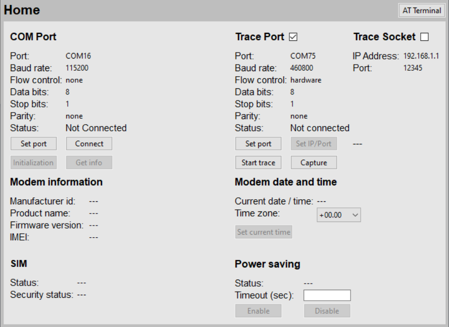
The Home page is the main page of the program. From here you can connect the m-center to an Evaluation Kit (EVK), start a modem trace, and display the module information. On the same page, you can configure the COM ports, the PIN usage, the module date and time, and the power saving.
The Home page includes the following sections:
COM Port
You can configure both the AT and Primary TraceLog COM port settings by clicking the Set port button. Configure the COM port only when m-center is not using the port (i.e. the Connect button has not yet been clicked). The port settings are saved when exiting the m-center. The upper side of the window displays the current COM port and the Trace port settings.
The following buttons are available in the "COM Port" section:
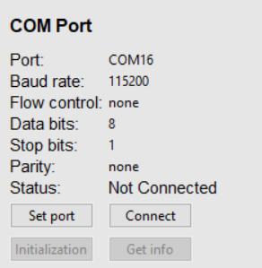
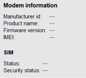
Modem information - After the AT port is connected and the "Initialization" or the "Get Info" operation is performed, this section displays the information about the connected module (manufacturer identification, product name, firmware version, and the module's IMEI, GSMA TAC model, GSMA model ATI7 if enabled from settings). The status bar also briefly displays the module information. At any time this information, as well as the network information shown in the top status bar, can be updated by clicking the Get Info button.
Auto Initialize Modem is added in the Settings menu and by default, it's enabled, to auto initialize the modem with basic commands when connected with m-center.
SIM - This section allows you to enter the PIN to the module, enable/disable the module SIM lock, as well as to change the PIN.
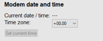
Modem date and time - This section displays the current module's date and time. By clicking the button Set current time, you can set the PC system time in the module, and also select the time zone.
The changes only have an effect if the SIM card is inserted into the module.
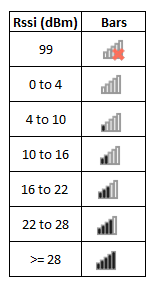
Signal bars on the Home panel depend on the RSSI value received from the modem. The signal bar value depends on the below table.
To show the latest stable firmware version of a modem, a JSON firmware file is managed. This file is present at 'workspace_directory\.mcenterws\json' with the name 'mc-fwmdm.json'.
The file lists the latest firmware versions of many u-blox modules. When the Get info, Initialization, or Connect (when Auto Initialize modem is selected) Button is pressed, it collects modem information including the firmware installed and displays the latest stable firmware on top in red color if the modem firmware doesn't match with the latest firmware listed in JSON file.
If the modem is not listed in the JSON file, no text will appear in red.
Below is an example.

m-center is able to capture the trace diagnostic information that is sent by u-blox modules over a specific serial interface. Follow the next steps to configure the trace channel and operation.
☛Run m-center in admin mode if collecting trace and ram dump.
☛Trace will not stop if USB/UART port (trace port) is disconnected.
When the trace port is disconnected, the m-center tries to reconnect 10 times, with an interval of 30 seconds. If the port does not appear at this time (30 * 10 = 300 sec = 5 minutes), then the tracing is stopped and a prompt is shown that the tracing has stopped.
Trace Port / Trace Socket - The Trace operation can be performed alternatively on the COM port or over an IP socket. Select the Trace Port or Trace Socket by selecting the proper check box. When the COM port is selected, the port settings can be changed by clicking the Set Port button. When the Socket mode is selected, you can change the IP address and port by clicking on the Set IP/Port button.
Start / Stop trace - Click on the Start Trace button to start a binary trace. A dialog box opens to ask for the trace filename to be used for storing the module trace. By default, the trace file is stored in the m-center folder named "trace" with "mc-trace" as the name and the file extension is determined by the modem protocol, e.g. *.istp ,*.bin , *.sdl and *.qmdl. After the trace recording begins, the Start Trace button changes its name to "Stop Trace".
Trace protocol check -During the trace operation the consistency of the trace data is checked. As the trace data protocol is not the same for all modules, the module type must be identified through the AT port. If the AT port is not available, m-center will perform the trace operation according to the "Trace default protocol" setting which is defined in the Settings menu.
Trace AT commands - m-center by default sends appropriate AT commands to the AT port in order to properly set the trace operation. The sending of these commands can be disabled (or enabled) using the "Trace AT commands" item in the Settings menu.
During the trace operation, the trace file size is shown together with the trace data transfer speed. The consistency of the trace data is checked and the file size of the trace log is continuously updated. If the data flow being analyzed does not match a known trace protocol, the message "Trace Log NOT VALID" will appear. A valid trace will issue the message "Trace Log Valid". If the file size fails to grow, or the trace data is not valid, consider disconnecting the trace port and trying another port.
- On TOBY-L1 / MPCI-L1 / SARA-G4 / SARA-N3 the trace check cannot be performed.
- On LEON / SARA-G / SARA-G4 / SARA-N3 the Trace operation can only be performed on the UART COM port.
- On LISA-U / SARA-U / TOBY-R2 / LARA-R2 series the Trace operation can be performed on both UART COM and USB CDC-ACM ports.
- On TOBY-L4 / TOBY-L2 / MPCI-L2 the Trace operation can be performed on UART COM, USB CDC-ACM, and socket.
- On LARA-R3 / SARA-R5 the Trace operation can be performed on both UART COM and socket.
- On LENA-R8 the Trace operation can only be performed on Unisoc USB Serial Port.
SARA-G4 / SARA-N3 - For Tracing baud rate 921600 and xon-xoff flow control shall be set on the UART COM port.
LENA-R8 - Flow control shall be none and it shall be connected with USB UNISOC Serial Port.
Port 4 shall be connected if 'Standard command' set as 'Trace Configuration' in 'Settings'.
Port 3 shall be connected if 'Advance command' set as 'Trace Configuration' in 'Settings'.
TOBY-L4 - Trace operation can be performed on UART COM, USB CDC-ACM, and socket.
For tracing on the socket (CDC-NCM) use IP 192.168.2.16 and port 41000.
For tracing on the socket (RGMII) use IP 192.168.90.60 and port 41000.
LARA-R2 / TOBY-R2 / SARA-U / LISA-U - Trace operation can be performed on UART COM and USB CDC-ACM.
For tracing on USB CDC-ACM set +USIO variant to 0 (default).
For tracing on UART set +USIO variant to 1. The following AT commands must be issued over an AT interface before starting the acquisition.
TOBY-L2 / MPCI-L2 - Trace operation can be performed on UART COM, USB CDC-ACM, and socket.
For tracing on UART and USB CDC-ACM set +UUSBCONF variant to 0 (default) and +UBMCONF variant to 1 (default). Must not issue any further AT commands in order to perform the desired tracing: in fact, all the configurations are automatically handled by m-center.
For tracing on the socket use IP 192.168.1.1 and port 12345 with +UUSBCONF variant to 3.
The following AT commands must be issued over an AT interface before starting the acquisition.
LARA-R3 - Trace operation can be performed on UART COM and socket.
For tracing on the socket use IP 192.168.10.1 and port 50000 with +USIO variant to 0 (default).
For tracing on UART set +USIO variant to 2 (only tracing available over UART).
The maximum allowed baud rate for tracing on the UART COM is 921600.
The following AT commands must be issued over an AT interface before starting the acquisition
SARA-R5 - Trace operation can be performed on UART COM and socket.
For tracing on the socket, use IP 192.168.10.1 and port 50000 with +USIO variant to 0 (default).
For tracing on UART, set +USIO variant to 3. The following AT commands must be issued over an AT interface before starting the acquisition. The maximum allowed baud rate for tracing on the UART COM is 921600
Available +USIO configurations for SARA-R5:
From the menu, you can select the trace configuration for SARA-R5 to filter the traces.
The available filters are:
As an alternative to the Trace operation, a simple capture can be performed by clicking on the Capture button. In this case, the data is saved to a file without performing any trace setting and without checking the consistency of the data received. Capture is supported on UART COMs, USB Ports, and TCP Sockets.
This page displays the network information and lists the available network operators. From here you can manage the packet-switched data (PSD) profiles.
Network Information
This section displays the operator name, the registration status, the operator selection mode, the RSSI, the radio capabilities (GPRS, UMTS, EDGE...), and the cell information (LAC, CI).
Click the Refresh Info button to update the information.
Network operators list
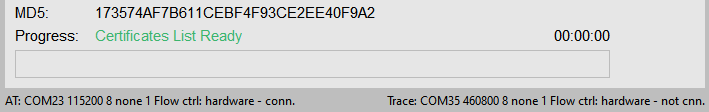
This section allows you to view all the networks available on the module. This operation is not automatically performed. To get the operator's list, click the Get List button. As this action can take some time, a pop-up dialog will appear during the network search. You can abort the operation by clicking on the Abort button.
When the network list has been populated, you can select an operator (if allowed) by clicking on Select Op. button. The operator selection sets the selection mode to manual. You can return to automatic search mode by clicking the Set auto mode button. You can also deregister the module from the network by pressing the Deregister button. Because all these actions can take some time, the wait dialog will appear, giving you the possibility to abort the operation.
PSD profiles
Click the Refresh button to see a list of all the configured GPRS profiles. Both internal and external profiles are shown. To edit or activate the GPRS profiles, select a profile on the table and click the Edit or Activate button. The dynamic IP address is shown after the profile activation. When a profile is activated, you can deactivate it by clicking the Deactivate button.
The Phonebook page provides a view of the SIM phonebook and lists the most recently dialed (mobile-originated) calls.
The m-center by default does not load the SIM phonebook and the last dialed calls list. To load the phonebook details, click the Get List button. After a few seconds, the table is filled with the phonebook entries.
Editing the SIM phonebook
These actions can be performed on the SIM phonebook by clicking the buttons at the bottom of the entry list.
Sending SMS to phonebook number
An SMS can be sent to the number selected in the SIM phonebook or in the Last dialed calls list by clicking the SMS button. In this case, the m-center switches to the SMS page (see next paragraph for SMS operations).
This page allows you to send text messages (SMS), manage the received messages, and set the message service center number.
Send text message
After the insertion of the message text and the destination phone number, click the Send button to send the message. To clear the Text in the textbox, click the Clear button. SMS text for normal text can be up to 147 characters. SMS text for special characters is supported up to 64 characters.
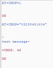
Manual sending of SMS
For sending SMS without the help of GUI, the AT terminal shall be used.
Message list and text
The table on the right lists all the received text messages. To list all the received SMSes click the Refresh button. To read a message just click on it and the box below the table shows its content.
To delete a message, select it in the list and click the Delete button.
After clicking the Reply button, the "Destination phone number" box on the left of the window is automatically filled with the phone number of the received SMS.
Short message service center
The message service center number allows you to send the text message. Even if it is usually automatically detected, because it is stored on the SIM card, you can configure this number by modifying it by clicking the Set button.
SMS notification - SMS notification can be enabled or disabled by clicking the Enable / Disable button on the lower right part of the window. If the SMS notification is enabled and the option "Automatic reading of RX SMS" is selected, a pop-up will appear when the module receives a message. The pop-up shows the SMS text.
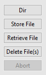
On this page, a simple File System Manager is implemented. The files in the module's File System can be displayed, copied to or from your PC. When a module is connected with m-center, you can perform various operations:
A tag can be defined in the Tag box (e.g. User, Audio, etc.) at the top right side of the panel. The tag permits work with application-specific files. Not all modems support tags. If a tag is not supported when performing a File System operation, an error message will be issued.
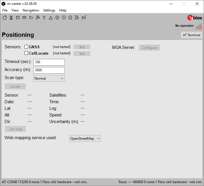
The Positioning in the m-center allows you to locate the module through the available sensors.
Sensors
The following sensors are available to perform the positioning functionality.
GNSS
CellLocate®
The corresponding Test button against every sensor can be used to verify the sensor availability. MGA Server can also be configured.
The following settings are available to set the necessary configurations for the Locate functionality.
Timeout (sec)
Accuracy (m)
Scan type (normal | Deep)
In the "Web mapping service used", you can select "OpenStreetMap" and "Google Maps" from the dropdown list.
The test for the CellLocate® feature requires a PSD context activation. (If no context is activated, you can define a new one and activate it on the Network page). A pop-up box displays the result of the availability test.
Localization
FOTA (Firmware Over The Air) is a procedure for updating firmware on a connected electronic device, such as on mobile phones and tablet computers.
In m-center, the FOTA demo application upgrades the cellular module firmware by retrieving a "delta file" from an FTP server and upgrading the firmware using this delta file.
To start the FOTA application, click the FOTA On button in the upper left corner of the page. When the FOTA application starts, the m-center checks if the module is registered on the network and if a PSD context is active. If there is no registration or no context is active, the FOTA application exits. A PSD context can be activated using the script.
On the left side of the page, there is a FOTA Log box, where all the FOTA operations are listed. To clean the FOTA log click the Clear Log button.
Encryption: Only use plain FTP (insecure) connection.
Retrieving a delta file from an FTP server
You can trigger the FOTA download operation by sending a "Download SMS" to the module connected to the m-center. This SMS shall start with the text tag defined in the Download FW Tag box. The default value of this tag is "FOTADWN", but it can be changed by editing the relative box.
The SMS format is:
<Dwn SMS Tag> : <FTP server address> , <FTP server username> , <FTP server password> , <FTP server path> , <Delta file name>
Example:
FOTADWN:123.123.123.123,Lisa,mypassword,dload/fw,Delta_MSY_FW_91.02_to_91_01_F.upd
In this demo application concatenated SMSes are not supported.
The port number information can be optionally added in the<FTP server address> field using this syntax: <FTP address>: <FTP port> (e.g. 123.123.123.123:8080).
In the FTP Data section, the fields will be filled with the data received from the SMS. The User Nr box will contain the user number. At the "Download SMS" reception, the m-center connects to the FTP server and downloads the delta file from there.
After a successful firmware download, an acknowledgment SMS will be sent to you that triggered the download. The delta file can be manually downloaded by clicking on the Manual FTP download button after having filled the FTP Data section with the FTP data and the filename fields.
Upgrading the firmware
You can trigger the upgrade process by sending an "Upgrade SMS" to the module connected to the m-center. This SMS shall start with the text tag defined in the Upgrade FW Tag box.
The default value of this tag is "FOTAUPG", but it can be changed by editing the corresponding box.
The SMS format is:
<Upg SMS Tag> : <Delta file name>
Example:
FOTAUPG:Delta_MSY_FW_91.02_to_91_01_F.upd
In this SMS, the only data sent is the filename of the delta file, which must be stored in the FS.
The firmware upgrade can be manually triggered by clicking on the Manual FW upgrade button after having filled the FTP Data section with the filename field. During the FW upgrade process, the status bar at the lower left part of the window shows the upgrade progress indication.
After a successful upgrade, the module is rebooted. The m-center will ask for the PIN code if the PIN has been previously enabled. If an SMS triggered the upgrade, an acknowledgment SMS with the new firmware version is sent to you.
The complete operation is possible to perform a download and an upgrade operation by means of an SMS that starts with the text tag defined in the Dwn+Upg FW Tag box. The default value of the tag is "FOTAALL".
The SMS format is:
<Dwn+Upg SMS Tag> : <FTP server address> , <FTP server username> , <FTP server password> , <FTP server path> , <Delta file name>
Example:
FOTAALL:123.123.123.123,Lisa,mypassword,dload/fw,Delta_MSY_FW_91.02_to_91_01_F.upd
After a successful upgrade and the module reboot, an acknowledgment SMS with the new firmware version is sent to you.
The FOAT (Firmware Over AT) procedure permits the upgrade of the firmware using the AT commands.
The feature currently available for the following u-blox cellular modules:
If a higher baud rate is required in the FOAT section, to speed up the larger file transfer, set the desired supported baud rate by the command in AT terminal section. e.g. AT+IPR=921600. This baud rate will also be reflected in the FOAT section.
- Once opened, FOAT section will automatically detect the cellular module connected.
- Based on the "Product name", the file extension that can be selected will be arranged accordingly.
- After the selection of the correct file for FOAT update, a pop-up will alert that the FOAT process will be initialized after clicking "Yes".
- Note that the updating process may require several minutes from start to end.
- FOAT Log window, on the right-side, will display all the important steps in the FW update process.
- By clicking on "Abort", the procedure will be interrupted.
- Once the procedure is completed, the green bar will be cleared and the "Firmware upgrade Completed: SUCCESS" message will be displayed in the FOAT Log window.
- For SARA-R5 ".upd" file is supported.
This section can be used when a cellular modem is either connected (online mode) or not connected (offline mode).
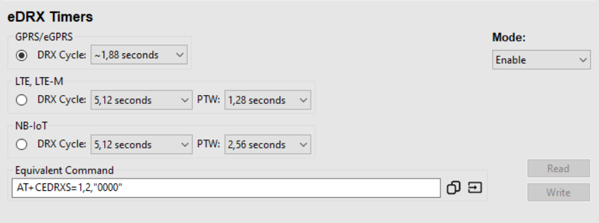
This section can be used when a cellular modem is either connected (online mode) or not connected (offline mode).
Connect the modem with the m-center in the Home tab, and open the "PSM and eDRX Timers" tab.
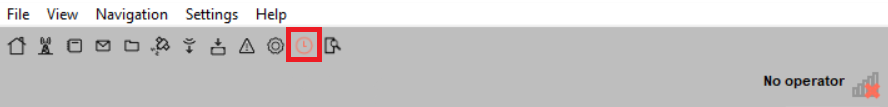
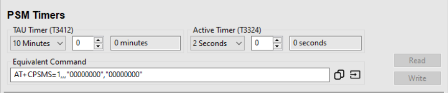
Read / Write buttons are enabled only when the modem is connected.
Read / Write buttons are enabled only when the modem is connected.
This section manages the X.509 certificates and private keys with the following functionalities:
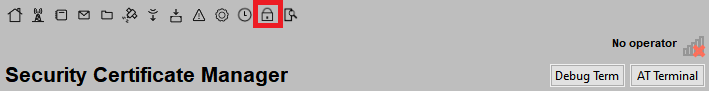
The following button functionalities are available in this Security Certificates Manager tab as shown below figure.
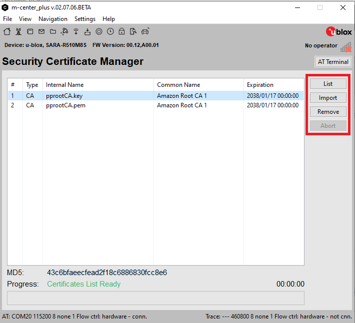
List: List down and information retrieval of imported certificates and private keys.
Remove: Removal of selected certificates and private keys from the populated list.
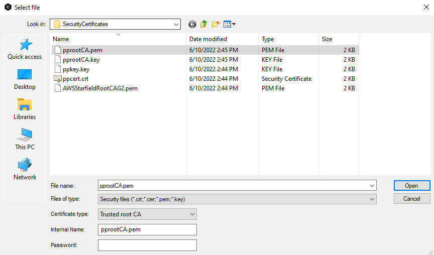
Import: Import the certificate from disk while the following types of certificates can be imported.
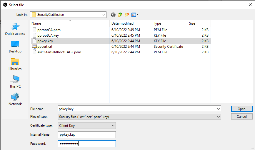
The following is an example of importing certificates. The multiple file selection to import is available.
Abort: Stop the List operation (List and information retrieval of imported certificates and private keys).
The device monitoring section provides diagnostic information on the GSM, UMTS, or LTE serving cell and on the neighbor's cell, along with channel and network environment description. If the module is camped on a PLMN (regardless of its registration status), it conveys the main attributes of the serving cell and of the neighbor cell.
"mc-monitor.dat" is the configuration file present under the installation directory \config\mc_default_config\mc-monitor.dat for adding/changing the AT commands and response parsing for specific modems. The configuration file is divided into group | Conf | cmd | resp |urc sections. You can add its required modem into the group, further adding the Conf, cmd, URC, and resp sections. A few of the default configurations are already present in the configuration file. You can also edit commands and responses by pressing the edit commands and responses icon.
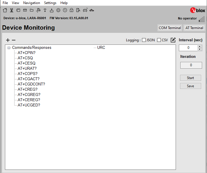
The following functionalities are available in the device monitoring section.
Interval (sec)
You can set the interval in seconds to refresh the device monitoring values for the attached modem. m-center will send all predefined commands from mc-monitor.dat and refresh the values after this defined time interval.
Start
Starts the device monitoring process by sending predefined commands to the attached modem.
(+)
Expands the populated list control, to show all the populated values.
(-)
Collapse the populated list control.
Save
Save the device information on disk with the default file name "device monitoring.txt" having the same tabular format shown in the tab.
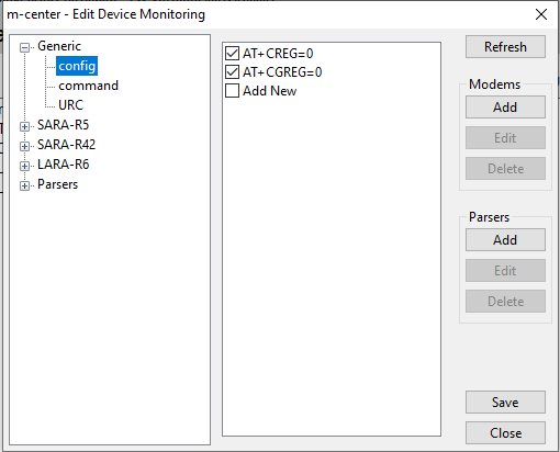
Edit commands and responses icon
This gives us the option to edit the config, commands, URC, and their response parsers of Generic and different modems.
JSON Logging
On checking the 'JSON' a file will be made in 'workspace_directory/log/dev_monitoring' in JSON format when the Start button is pressed.
CSV Logging
On checking the 'CSV' a file will be made in 'workspace_directory/log/dev_monitoring' in CSV format when the Start button is pressed.
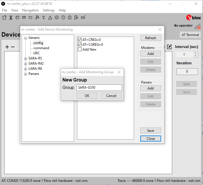
1. Go to the Device monitoring tab.
2. Press the Edit Commands and Response icons.
3. Press Add button in the Modems section.
4. Enter the Modem name in the pop-up. e.g. SARA-G350.
5. Press the OK Button. SARA-G350 will appear in the list of modems.
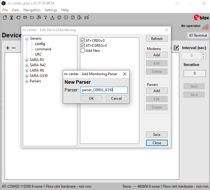
1. Press Add button in the Parsers section.
2. Enter the parser group to be added name e.g. parser_CEREG_G350.
3. Press the OK button.
4. Press the Save button.
5. Press the Edit commands and responses icon again. Verify the newly added Parser group is added in Parsers.
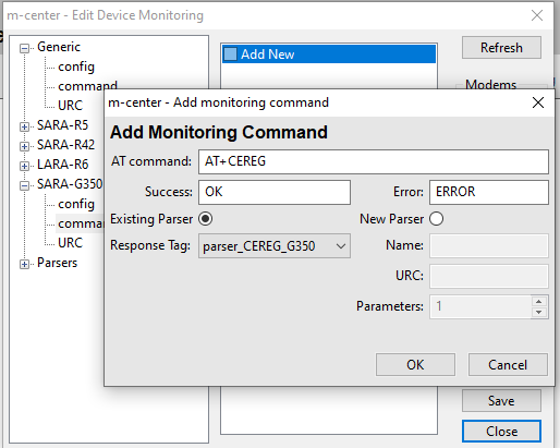
1. Select the newly added Modem e.g. SARA-G350.
2. Select command.
3. Double-click Add New.
4. Enter the AT command and select the newly made Response tag.
5. Press OK. Save and close the edit window.
6. Now on pressing the Start button, the newly added command will be sent on each interval if the modem (SARA_G350) is connected with m-center.
This page allows you to run an IVS (In-Vehicle System) simulator. It is a system that, in conjunction with a PSAP (Public Safety Answering Point), is capable of sending a simulated eCall (emergency Call) and the MSD (Minimum Set of Data) transmitted within the eCall.
IVS on / IVS off button
Initializes and enables the eCall feature in the modem. Initialization includes the execution of AT commands specified in the eCall control: "Init file list"
eCall control panel
The panel is active when IVS is on.
eCall control: Call Start
A button that triggers the emergency call and MSD sending towards the PSAP number, in either PUSH or PULL mode.
eCall control: Init file list / Initialize button
The drop-down menu shows the option of initialization scripts, while the Initialize button executes the currently selected script. Custom scripts can be stored in "\par\ivs" folder, with extension .ivsi.
eCall control: eCall type
Selection of MieC (manually triggered), AieC (automatically triggered) or test emergency call. This information is provided both to the network (eCall flag) and to PSAP (encapsulated in the MSD)
eCall control: Autoanswer
With this option, you can enable and configure (PUSH/PULL) the auto answer at PSAP callbacks.
eCall control: Redial on busy, drop...
The redial feature according to PAN EU eCall.
eCall control: Audio control
Selection for internal or external voice switching. Internal switching is recommended.
eCall control: HLAP timers
Configuration of HLAP timers when external voice switching is enabled.
eCall control: MSD update on PULL
If "MSD update on PULL" is selected, the IVS simulator implements the MSD update upon reception of the PULL request from PSAP.
eCall control: MSD update on GNSS
With this option, the MSD update is continuous at the GNSS fix rate.
eCall control: Manual MSD update
A manual trigger of an MSD update is possible by pressing the MSD upd. button. If "Force MSD update" is selected and the update is requested while eIM is transmitting an MSD, the transmission is interrupted, eIM transmitter resets and restarts with the new MSD.
eCall control: MSD optional data
With this option, the Optional data will be included in the MSD. This feature is still experimental.
MSD Version list box
In this list box the MSD Version 2 or MSD Version 1 - ERA GLONASS option can be selected.
MSD --> SMS button The MSD is sent through an SMS. If the Version 1 - ERA GLONASS option is selected, the MSD is encapsulated into the SMS message text accordingly to the transport protocol defined in GOST R 54619-2011 specification.
GNSS panel The GNSS panel controls the GNSS sub-system (if connected to the modem) and presents the acquired GNSS data. m-center configures the GNSS and receives data from it through the dedicated USB/UART port.
GNSS panel: SetPort
Select the GNSS USB/UART port.
GNSS panel: GNSS checkbox GNSS can be activated by enabling the "GNSS" checkbox.
Show MSD button: eCall MSD window
The eCall MSD window appears. This window shows the decoded content of the MSD sent to the remote PSAP. The window is updated when the MSD transfer starts.
The window is divided into three parts: Top, Middle, and Bottom panels.
Top panel: MSD cnt
This MSD field (message identifier) counts the MSDs sent during each eCall transaction. The field is automatically updated by the IVS simulator.
Top panel: Activation
This field shows the MieC/AieC field sent in the MSD according to the configuration in eCall control: eCall type.
Top panel: eCall
This field shows the emergency/test field sent in the MSD according to the configuration in eCall control: eCall type.
Top panel: VIN, Nr of passengers, Veh. Type, Propulsion
These MSD fields must be manually configured through this window.
The VIN code syntax is checked at transfer time. VIN code is cropped if not supported chars are entered.
Middle panel
This panel shows the GNSS data. If the GNSS is switched on, the fields are automatically updated when the MSD transfer starts. If the GNSS is switched off, the location data fields can be edited manually, while the timestamp is always set to system time.
Bottom panel: Optional data
The Optional data text box can be activated with the MSD optional data checkbox in the eCall control panel.
With this edit box, you can manually add optional data in the MSD. This feature is still experimental.
In the case that MSD Version 1 - ERA GLONASS option is used, the optional data is formatted accordingly to GOST R 54620-2011 specification and represents the RTA severity estimation. Three hex numbers separated by a comma can be written in an optional data textbox (eg. 1, 18c, 1a). These numbers specify three bitmasks relative to Severe crash estimation (1 flag), Test Results Def (21 bits), and Crash Def (6 bits).
Bottom panel: MSD files list
This drop-down menu explores the \par\ivs directory for selecting pre-formatted binary MSDs or textually-described MSDs (.msd).
Bottom panel: MSD file name and Save MSD
The content of the eCall MSD window can be saved on a .msd file. Do not provide a .msd file extension in the MSD file name dialog box.
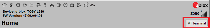
To open the AT terminal window, click on the AT Terminal button at the upper right of the m-center window.
The terminal data panel displays all the communications between the m-center and the module. All the data sent to the module are displayed in BLUE text, while the data received from the module are displayed in RED text. For generic info, GREEN text is used. To clear the contents of the terminal data panel, click the Clear Terminal button.
AT commands can manually be entered or chosen in the AT command list on the right side of the window.
Clicking the close icon in the upper right corner of the AT terminal window hides the terminal, although it remains active.
Home Icon on the top left of the window. By pressing this button the control from AT terminal is shifted to the m-center main window.
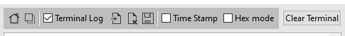
Terminal log
On the top left of the window, there is a checkbox that enables/disables the AT terminal log. Its value is persistent at m-center closing and restarting. The log is by default enabled and saved at user-profile location [.mcenterws]/log/ with filename mc_at.log. Upon exit, m-center makes a copy of the log file in the "log" folder, adding a timestamp to the filename. The reference path could be easily accessed through the "Open Workspace Location" functionality available in the "File" menu.
Enable/Disable stay on top icon make sure the AT terminal windows stay on top always on the Home window.
The Terminal Log check box controls the saving of running logs in a log file. Timestamps of log commands can also be enabled/disabled by setting the parameter "TimeStamp_Log" to 1/0 respectively, in the "mc-io.par" file.
Open current log file icon opens the current log file in a default text editor.
Stop writing current log file icon saves the existing log in mc-at_<timestamp> and creates a new log file.
Save As icon choose another log filename and path. This saves the log collected so far to the new file and continues logging in the "mc_at.log" file.
Time Stamps
Time Stamps can be selected with the checkbox located on the upper side of the window. By default on the first installation, it is set to be enabled. If enabled/disabled and m-center is closed, the newly started m-center will retain enable/disable value.
In time stamps mode, all the transmitted and received data are shown with stamps of the respective time. The AT terminal log also reflects this setting.
Hex mode
Hex mode can be selected with the checkbox on the upper side of the window. By default on the first installation, it is set to be disabled. If enabled/disabled and m-center is closed, the newly started m-center will retain enable/disable value.
In Hex mode, all the transmitted and received data are shown in both hex and text format. The AT terminal log also reflects this setting.
Entering commands
AT command list
On the right side of the AT Terminal window, there is a list of predefined AT commands. The commands are arranged into many groups, which can be selected in the drop-down list in the upper right corner.
Double-click the command to send it directly to the COM port. Single-click the command to copy it in the input text box. While adding the AT command three things are added. It's command, comment, and Title. If Title is present it will be displayed in the list otherwise the AT command will be displayed.
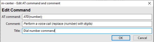
AT command list editing
As a feature of the m-center tool, the editing and the customization of both AT commands and group lists is feasible and it can be achieved in two different ways. In both procedures, the modifications will be stored for any future use of the m-center.
The first option, which is the simplest one, is available referring to the editing buttons present on the lower right part of the AT Terminal interface and here below described. This first choice is recommended if the number of AT commands to add or edit is limited.
The second option, to edit the AT command list is preferable if a large number of commands must be added. To proceed with this option, the m-center application must be quitted and kept closed. All the AT groups, commands, and comments are stored in the m-center "par" folder, i.e. in the file "mc-atlist.par". If this file is removed, the default command list "mc-atlist.dat", located in the m-center root folder, will be used to restore the initial AT commands and groups. This file can be edited separately using a simple text editor: in fact, by applying the proper format, AT groups can be created and multiple AT commands can be added. Once the "mc-atlist.par" file is saved and the edit is completed, m-center can be executed from scratch and all the inserted changes will be reported in the AT command interface. AT commands can also be imported from other files to the "mc-atlist.par" one by using the Import Commands button.
In the "mc-atlist.par" file editing, Strings and Hex bytes can also be added in the AT commands definition associated to a group taking into account the following format:
String:
item|group|ST : This is a string|Send string: "This is a string"
Hex:
item|group|HX : a1 b2 cc 44 ef|Send hex data: a1b2cc44ef
Flow Control Lines
The controls of the com port flow control lines are placed at the bottom right of AT terminal window.
There are seven control lines: RTS, DTR, CTS, DSR, RI, DCD & BRK. When the COM port flow control is set to "hardware" the system takes control of DTR and RTS lines, otherwise, they can be set manually. For the remaining lines, only their status can be observed. BRK sets the break signal of the port if checked and resets the break signal when unchecked.
These flow control lines can be enabled or disabled from the setting menu using the "Enable/Disable COM port lines" option. Once these lines are disabled it will remain as it is, regardless of the flow control setting from "Set Port".
When the Enable COM port lines are selected, the DTR control line is asserted (checkbox with flag) as the initial value. The DTR check-box is enabled if Hardware flow control, so DTR can be toggled freely as desired for debugging purposes.
Termination Character
The termination character settings are available under the menu (Settings->Termination Character), and the following options are available.
AT Scripting panel is available at the bottom of AT terminal. Start the selected AT Script from a drop-down control. A number is AT Scripts are present in the installation directory (default) while the Git download option is also provided during the installation of m-center. The Git repository always has the latest version of AT Scripts. These scripts are provided for demonstration and debugging purposes only.
The AT Scripts are text files having selected AT commands to execute to perform a specific operation/functionality. Every AT command listed will be executed one after the other starting from the first one. Before executing an AT command, the m-center will wait for the response of the previous AT command. Once a maximum timeout expires, the script will be aborted, and the remaining commands will not be sent to the connected modem.
The following button functionalities are available to Refresh, Open the AT Scripts folder, download from Git and Edit the AT Scripts.
The following selectable properties are available in AT Scripting section as in the below figure.
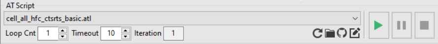
The following iconic button functionalities are available in AT Scripting section as shown in the above figure.
Start/Resume: Start/resume the selected script in AT Script dropdown.
Pause: Pause the running script.
Stop: Stop the running script.
If AT script is running and you disconnect the modem port, a message is displayed to warn you that
"AT Script is running, do you want to stop the AT Scripting also?" with Yes|No|Cancel options.
AT Scripting GitHub is defined to maintain all useful scripts that can be shared with everyone for testing and debugging purpose.
The GitHub icon is present in the AT script section. On click event of this icon, u-blox/m-center main repository (m-center-main.zip) will be downloaded at the user-specific path.
You can also clone scripts from GitHub using the following commands:
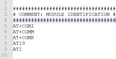
While writing your first AT script, please follow the guidelines below
A basic sample AT script is written below.
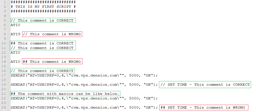
Follow the below rules for commenting in AT Script file.
This section is for advanced users, for reference purposes. The related script development support is to not be granted.
All the following reported methods are taken from the AngelScript implementation. This scripting language follows the widely known syntax of C/C++. For this reason, you can use the common C/C++ datatypes for efficient communication.
This link contains all information about statements like variable declaration, selection statements (if and else), and iteration statements (loops).
In order to define the modem's specific scenarios like sending AT command, waiting for a specific response, or finding the string, some custom macros are also defined in scripting. Use this link to get details about all custom macros.
A macro is implemented as MC_EVK_D2XX(string function, int action), which will support performing different modem and EVK hardware operations.
To get details about COM port open/close, start/stop tracing, or m-center GUI control using scripting follow this link.
Moreover, all programming-related guidelines are available at the following link.
If a function is defined in an AT script, the main function is mandatory and must be defined in it. Otherwise, the script will return an error.
The following short keys are available in different functionalities of m-center.
AT Terminal:
AT Scripting:
File Menu:
Settings Menu:
Help Menu:
File
Open Workspace Location
It opens the workspace location. i.e. C:\Users\ <User> \.mcenterws. The shortcut key is Ctrl+W.
Open Trace Location
It opens the trace location inside the workspace folder. i.e. C:\Users\ < User> \.mcenterws\trace. The shortcut key is Ctrl+T.
Open Script Location
It opens the AT script's location inside the workspace folder. i.e. C:\Users\ <User> \.mcenterws\at_scripts. The shortcut key is Ctrl+Alt+O.
Open Application Location
It opens the application's installed location. i.e. C:\ <InstallationDirectory> \u-blox\m-center. The shortcut key is Ctrl+O.
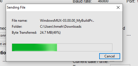
Send File
Send the selected file to the modem. The shortcut key is Ctrl+F. This function supports sending files to the module file system, FTP, socket, etc.
Restore Default Settings
It restores the default settings of the m-center application.