

NORA-W36 u-connectXpress user guide
NORA-W36 u-connectXpress
Stand-alone multiradio modules
User guide

This document provides an overview of the u-connectXpress software for u-blox short range modules
and describes how the products can be configured for Wi-Fi and Bluetooth Low Energy use cases.
Document information
| Title | NORA-W36 series u-connectXpress |
|---|---|
| Subtitle | Stand-alone multiradio modules |
| Document type | User guide |
| Document number | UBX-23008692 |
| Revision and date | R01, 28-May-2024 |
| Disclosure restriction | C1-Public |
This document applies to the following products
| Product name | Software version |
|---|---|
| NORA-W36 series | 1.0.0 or newer |
Disclaimer
u-blox or third parties may hold intellectual property rights in the products, names, logos, and designs included in this document. Copying, reproduction, or modification of this document or any part thereof is only permitted with the express written permission of u-blox. Disclosure to third parties is permitted for clearly public documents only.
The information contained herein is provided “as is” and u-blox assumes no liability for its use. No warranty, either express or implied, is given, including but not limited to, with respect to the accuracy, correctness, reliability, and fitness for a particular purpose of the information. This document may be revised by u-blox at any time without notice. For the most recent documents, visit www.u blox.com.
Copyright © u-blox AG
1 Overview
This document describes how to set up and use u-blox short range stand-alone modules with u-connectXpress software for NORA-W36. It explains the functionality of different u-blox short range stand-alone modules and includes examples that describe how to use the software in different environments with AT commands. The document is applicable for Bluetooth® Low Energy (LE), multiradio, and Wi-Fi modules.
Several u-blox short range stand-alone modules support open software variants. For more information about the available options, see the corresponding system integration manuals for u-blox short range stand-alone modules.
For older generation modules like ODIN-W2, NINA-W15 and ANNA-B1) u-connectXpress UG (UBX-16024251) describe the functionality of these modules.
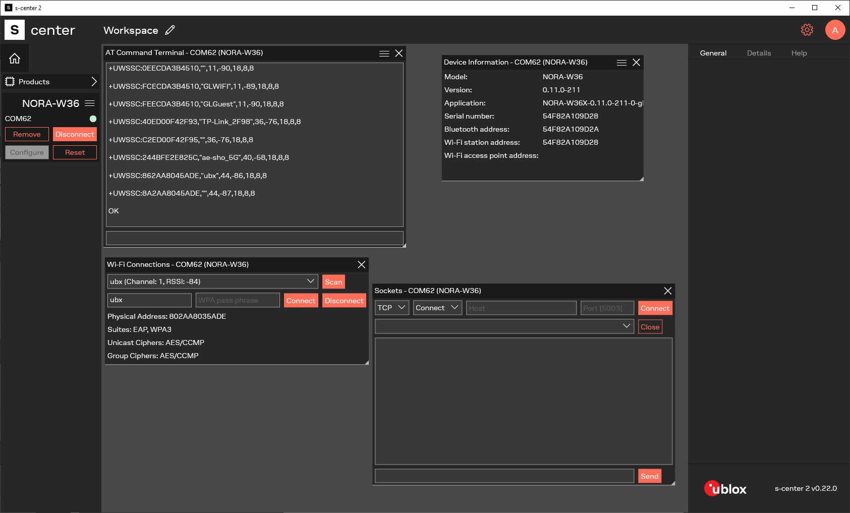
1.1 Getting started with s-center 2
Downloading and installing
- Download the latest version of s-center 2 here
- Double click the downloaded file and follow the installation instructions
- Launch s-center 2 when the installation is completed
1.2 Product description
u-blox modules are developed for integration into a vast range of devices that demand a high level of reliability, such as those that are typically used in industrial and medical applications.
These professional grade modules operate over an extended temperature range and are approved for radio type application products in many countries. By choosing to use u-blox short range stand-alone modules, the cost and work involved in developing wireless communication solutions is significantly reduced.
| Concept | Definition |
|---|---|
| Host | In this document, a host refers to the device connected to a u-blox short range stand-alone module through any of the available physical interfaces. In a real application, the host is typically a microcontroller Unit (MCU) running a customer specific application. |
| Module | In this document, module refers to a u-blox stand-alone module. A module can also refer to a self-contained unit or item that is linked with similar units of a larger system that performs a defined task. |
| Remote | device A remote device in a wireless network connecting over the Bluetooth Low Energy or Wi-Fi interfaces supported in the module. |
1.2.2 Multiradio and Wi-Fi modules
u-blox compact and powerful stand-alone, multiradio modules are designed for the development of Internet-of-Things (IoT) applications. NORA-W36 modules include an embedded Bluetooth stack, Wi-Fi driver, IP stack, and an application for wireless data transfer. The wireless support includes Bluetooth v5.3 (Low Energy) and dual-band Wi-Fi (2.4 and 5 GHz bands).
The modules support point-to-point and point-to-multipoint configurations and can accommodate concurrent Bluetooth and Wi-Fi connections. The software provides support for micro Access Point. Some modules also have support for interfacing the module through an SPI (Serial Peripheral Interface).
They are delivered with u-connectXpress software that provides support for u-blox Bluetooth LE Serial Port Service, Generic Attribute Profile (GATT) client and server, Bluetooth beacons, simultaneous Peripheral and Central roles – all configurable from a host by means of AT commands.
2 Key features
The possibility of replacing serial cables with simple wireless connections is a key feature of u-blox modules. It allows system hosts to transfer data to one another over wireless Bluetooth connections that are established between u-blox modules in Central/Peripheral configuration.
Depending on the module capabilities, data from each host is transferred to local u-blox modules over a serial UART interface.
u-blox modules can be configured to automatically establish new connections and/or accept incoming connections using AT commands. For connected hosts, this means that physical serial cables can be replaced with more convenient wireless solutions.
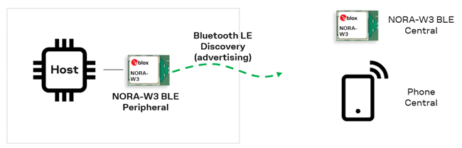
2.1 Bluetooth GATT connection
NORA-W36 can function as either a Central or Peripheral unit, connecting to devices such as laptops, cellular phones, and tablets using the Generic Attribut Profile (GATT).


2.2 Bluetooth SPS connection
NORA-W36 can function as either a Central or Peripheral unit, connecting to devices such as laptops, cellular phones, and tablets via the u-blox Serial Port Service (SPS).
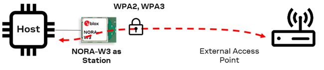
2.3 Wi-Fi station connection
NORA-W36 can operate as a Station connecting to an Access Point.

2.4 Wi-Fi access point connection
NORA-W36 can operate as an Access Point connecting to other devices are operate as Stations.
3 u-connectXpress software
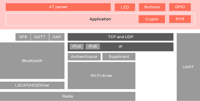
3.1 Software architecture
u-connectXpress software for u-blox short range stand-alone modules makes it easy to integrate Bluetooth and Wi Fi connectivity into both new and existing products.
In several high-end modules, u-connectXpress software contains separate stacks for the Bluetooth Low Energy (LE), wireless Transmission Control Protocol (TCP) and wireless Internet Protocol (IP). The necessary Wi-Fi drivers are also included. Other module variants support different combinations of these stacks.
The figure below shows the logical components for high-end (NORA-W36) modules.
3.2 Operating modes
NORA-W36 operates in the following modes:
- AT mode (default): AT commands and data can be send at the same time. Data is sent and received in AT commands and events - in string or binary mode
- Transparent Mode (TM): All data sent and received on the UART is connected to the remote device
- Transparent Mode Persistent (TMP): Same as TM, but the connection is established at startup or when the connection is dropped
Additionally, the module supports various low-power modes, which optimize power consumption regardless of the operating mode. See also Low power modes and Power consumption optimization.
In version 1.0.0 deep sleep is supported with the command AT+UPMDS, see AT command manual and Data sheet for more information.
3.2.1 Changing operating modes
u-blox modules can be configured to start in any operating mode. Once up and running, the modules can be switched between most modes. The modes are changed with a command or escape sequence sent to the module:
- Switch from Command mode to Transparent mode using an AT command
- Switch from Transparent mode to command mode with an escape sequence.
The module is controlled using AT commands in (default) Command mode. In this mode, the host sends control and configuration commands and indicates when data is to be sent over the UART interface.
3.3 NORA-W36 capabilities
| u-connectXpress features | Capability in 1.0.0 |
|---|---|
| Multiradio | Bluetooth Low Energy 5.3 and Wi-Fi 4 dual band 2,4 and 5 GHz |
| Wi-Fi Access Point | 5 Stations connected |
| TCP/UDP sockets | 3 Simultaneous sockets |
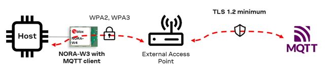
| MQTT Connections | 1 Connection (client) |
| BLE Central connections | 3 Peripherals connected |
| BLE Peripheral connections | 1 Central connected |
| BLE Scatternet connections (C+P) | Central with 1 Peripheral connected, advertising and allow incoming connection as Peripheral |
| BLE Link key storage | 30 Devices. The keys that are the least used are removed first when storage is full |
| Coexistence Wi-Fi, BLE and TLS | Max 1 TLS client, 1 BLE, 2 TCP Client |
| Data transfer modes | - Buffer Mode (event and read data) - Direct Mode (data in event) - Transparent mode (like serial port cable replacement) Buffer Mode is Default, Transparent mode only supports one link. Transparent Mode has highest throughput, then Direct Mode and then Buffer Mode |
| SPS MTU size | 244 bytes, 1000 bytes can be sent in AT command |
| TCP MTU size | 1460 bytes, 1000 bytes can be sent in AT command |
| u-connectXpress software components | Versions in 1.0.0 |
|---|---|
| Realtek SDK including Bluetooth stack and Wi-Fi drivers | 6.2 + patches eb65546, 03911c3, 6dfd87c, bf52a1f, 1bcc6de, 373f322, 0a63ad1 |
| lwIP TCP/IP stack | 2.0.3 |
| Mbed TLS cryptographic algorithms | 2.4.0 |
| u-connectXpress MQTT client | Versions in 1.0.0 |
|---|---|
| MQTT version | 3.1.1 |
| MQTT capabilities | Publish, Subscribe, TLS, QoS, Testament and Last will |
| MQTT maximum packets size | 730 bytes for Publish and Subscribe packets |
| u-connectXpress TLS feature | TLS capability in 1.0.0 |
|---|---|
| TLS version | Only TLS1.2 (TLS 1.3 is planned for future versions) |
| TLS max number of connections | 1 |
| TLS extensions enabled by default | Server Name Indication (SNI), Maximum Fragment Length Negotiation |
| TLS Encryption keys | Advanced Encryption Standard (AES). Data Encryption Standard (DES), Rivest Cipher 4 (RC4), and the Camellia cipher are not supported. |
| EAP-TLS certificate key size supported | 2048 bits (4096 bits can exceed memory limitations) |
| TLS over TCP certificate key size supported | 4096 bits |
| TLS certificates | Up to 8 certifications (or certificate chains) can be stored. Certificates can be maximum 15360 bytes. |
| TLS Cipher Suites (28suites) | TLS_ECDHE_ECDSA_WITH_AES_256_CBC_SHA384 (0xc024) TLS_ECDHE_RSA_WITH_AES_256_CBC_SHA384 (0xc028) TLS_DHE_RSA_WITH_AES_256_CBC_SHA256 (0x006b) TLS_ECDHE_ECDSA_WITH_AES_256_CBC_SHA (0xc00a) TLS_ECDHE_RSA_WITH_AES_256_CBC_SHA (0xc014) TLS_DHE_RSA_WITH_AES_256_CBC_SHA (0x0039) TLS_ECDHE_ECDSA_WITH_AES_128_CBC_SHA256 (0xc023) TLS_ECDHE_RSA_WITH_AES_128_CBC_SHA256 (0xc027) TLS_DHE_RSA_WITH_AES_128_CBC_SHA256 (0x0067) TLS_ECDHE_ECDSA_WITH_AES_128_CBC_SHA (0xc009) TLS_ECDHE_RSA_WITH_AES_128_CBC_SHA (0xc013) TLS_DHE_RSA_WITH_AES_128_CBC_SHA (0x0033) TLS_RSA_WITH_AES_256_CBC_SHA256 (0x003d) TLS_RSA_WITH_AES_256_CBC_SHA (0x0035) TLS_ECDH_RSA_WITH_AES_256_CBC_SHA384 (0xc02a) TLS_ECDH_RSA_WITH_AES_256_CBC_SHA (0xc00f) TLS_ECDH_ECDSA_WITH_AES_256_CBC_SHA384 (0xc026) TLS_ECDH_ECDSA_WITH_AES_256_CBC_SHA (0xc005) TLS_RSA_WITH_AES_128_CBC_SHA256 (0x003c) TLS_RSA_WITH_AES_128_CBC_SHA (0x002f) TLS_ECDH_RSA_WITH_AES_128_CBC_SHA256 (0xc029) TLS_ECDH_RSA_WITH_AES_128_CBC_SHA (0xc00e) TLS_ECDH_ECDSA_WITH_AES_128_CBC_SHA256 (0xc025) TLS_ECDH_ECDSA_WITH_AES_128_CBC_SHA (0xc004) TLS_RSA_PSK_WITH_AES_256_CBC_SHA384 (0x00b7) TLS_RSA_PSK_WITH_AES_256_CBC_SHA (0x0095) TLS_RSA_PSK_WITH_AES_128_CBC_SHA256 (0x00b6) TLS_RSA_PSK_WITH_AES_128_CBC_SHA (0x0094) |
| TLS Signature Hash Algorithms (10 algorithms) | ecdsa_secp521r1_sha512 (0x0603) rsa_pkcs1_sha512 (0x0601) ecdsa_secp384r1_sha384 (0x0503) rsa_pkcs1_sha384 (0x0501) ecdsa_secp256r1_sha256 (0x0403) rsa_pkcs1_sha256 (0x0401) SHA224 ECDSA (0x0303) SHA224 RSA (0x0301) ecdsa_sha1 (0x0203) rsa_pkcs1_sha1 (0x0201) |
| TLS Extensions | Server name (SNI) Max fragment length: 4096 (4) |
More information about the AT commands used in this use cases can be found in the NORA-W36 AT command manual.
| Supported modules | Software versions |
|---|---|
| NORA-W36 series | v1.0.0 |
4 Bluetooth use cases
The following Bluetooth Low Energy use case, show some functionality to get started with GATT client, GATT server and SPS.
| u-connectXpress BLE default values | 1.0.0 |
|---|---|
| BLE Mode default | ON, Central and Peripheral (3) |
| BLE Advertising default | OFF, enable with AT+UBTA=1 |
The following examples use the MAC address below, this must be replaced by the real MAC address of the devices that are used.
- Peripheral MAC address: AAAAAAAAAAAA
- Central MAC address: BBBBBBBBBBB
4.1 Bluetooth SPS central
This use case configures NORA-W36 as a Central device that sends and receives data from another NORA-W36 module operating as a Peripheral device. The communication between the two modules is facilitated using the proprietary u-blox Serial Port Service. It is also possible to connect to other devices that supports the SPS protocol.
This use case operates in combination with Bluetooth SPS peripheral.
| Nr | Instructions | AT command | AT event |
|---|---|---|---|
| 1 | Check that Bluetooth Central is enabled. 1:Central or 3:Central and Peripheral. If so, jump to step 6. | AT+UBTM? | +UBTM:1 or +UBTM:3 |
| 2 | Enable Bluetooth 1:Central or 3:Central and Peripheral | AT+UBTM=1 or AT+UBTM=3 | |
| 3 | Store command | AT&W | |
| 4 | Restart | AT+CPWROFF | |
| 5 | Wait for NORA-W36 to start | +STARTUP | |
| 6 | Initiate Bluetooth discovery. Listen for advertising packets broadcast from Peripheral device. | AT+UBTD | +UBTD:AAAAAAAAAAAAp,-52,"NORA-W36-AAAAAA",0,10094E4F52412D5733362D414141414141 |
| 7 | Connect Bluetooth | AT+UBTC=AAAAAAAAAAAAp | +UEBTC:0,AAAAAAAAAAAAp |
| 8 | Read MTU, maximum data size | AT+UBTCST=0,4 | +UBTCST:4,247 |
| 9 | Read RSSI (optional) | AT+UBTRSS=0 | +UBTRSS:-52 |
| 10 | Connect SPS using handle of Bluetooth connection | AT+USPSC=0 | |
| 11 | SPS connection is up | +UESPSC:0 | |
| 12 | It is now possible to send and receive SPS data in String or Binary mode | ||
| 13 | Disconnect the SPS and Bluetooth connection | AT+UBTDC=0 | +UESPSDC:0+UEBTDC:0 |
4.2 Bluetooth SPS peripheral
This use case configures NORA-W36 module as a Peripheral device that sends and receives data from another NORA-W36 module operating as a Central device. The communication between the two modules is facilitated using the proprietary u-blox Serial Port Service. It is also possible to connect to other devices that support the SPS protocol.
This use case configuration is used in combination with Bluetooth SPS central.
| Nr | Instructions | AT command | AT events |
|---|---|---|---|
| 1 | Check that Bluetooth Peripheral is enabled. 2: Peripheral and 3: Central and Peripheral. If so, jump to step 6 | AT+UBTM? | +UBTM:2 or +UBTM:3 |
| 2 | Enable Bluetooth 2: Peripheral or 3: Central and Peripheral | AT+UBTM=2 or AT+UBTM=3 | |
| 3 | Store command | AT&W | |
| 4 | Restart | AT+CPWROFF | |
| 5 | Wait for NORA-W36 to startup | +STARTUP | |
| 6 | Enable SPS on Peripheral | AT+USPS=1 | |
| 7 | Enable Advertisements | AT+UBTA=1 | |
| 8 | Peripheral receives Incoming Bluetooth connection | +UEBTC:0,BBBBBBBBBBBBp | |
| 9 | Read MTU, maximum data size on both | AT+UBTCST=0,4 | +UBTCST:4,247 |
| 10 | Read RSSI (optional) | AT+UBTRSS=0 | +UBTRSS:-52 |
| 11 | Central Connect SPS using handle of Bluetooth connection | AT+USPSC=0 | +UESPSC:0 |
| 12 | It is now possible to send and receive SPS data in String or Binary mode | ||
| 13 | SPS and Bluetooth link is down | +UESPSDC:0+UEBTDC:0 |
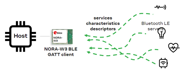
4.3 Bluetooth GATT client
This use case configures NORA-W36 as a Central device that operates as a GATT client and receives data.
This use case configuration is used in combination with Bluetooth GATT server.
| Nr | Instructions | AT command | AT event |
|---|---|---|---|
| 1 | Check that Bluetooth Central is enabled. 1: Central or 3: Central and Peripheral. If so jump to step 6. | AT+UBTM? | +UBTM:1 or +UBTM:3 |
| 2 | Enable Bluetooth 1: Central or 3: Central and Peripheral | AT+UBTM=1 or AT+UBTM=3 | |
| 3 | Store command | AT&W | |
| 4 | Restart | AT+CPWROFF | |
| 5 | Wait for NORA-W36 to startup | +STARTUP | |
| 6 | Connect to remote device | AT+UBTC=AAAAAAAAAAAAp | +UEBTC:0,AAAAAAAAAAAAp |
| 7 | Discover Services and look for 180D, which is the descriptor for the Heart Rate service. | AT+UBTGPSD=0 | +UBTGPSD:0,12,65535,180D |
| 8 | Discover all Service Characteristics and look for 2A37, which is the descriptior for the Heart Rate Measurement characteristics. | AT+UBTGSCD=0,12,65535 | +UBTGSCD:0,13,10,14,2A37 |
| 9 | Use the Value handle, which in this case is 14. The value can vary. Look for 2902, which is the descriptor for the notification. | AT+UBTGCDD=0,14,15 | +UBTGCDD:0,13,15,2902 |
| 10 | Enable notification on the GATT Client the Central in this example | AT+UBTGCCW=0,15,1 | |
| 11 | Notification is received on the GATT Client | +UEBTGCN:0,14,60+UEBTGCN:0,14,61+UEBTGCN:0,14,62 |
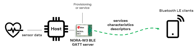
4.4 Bluetooth GATT server
This use case configures NORA-W36 as a Peripheral device that operates as GATT server and sends notifications.
This configuration works in combination with Bluetooth GATT client.
| Nr | Instructions | AT command | AT event |
|---|---|---|---|
| 1 | Check that Bluetooth Peripheral is enabled 2: Peripheral and 3: Central and Peripheral. If so jump to step 6. | AT+UBTM? | +UBTM:2 or +UBTM:3 |
| 2 | Enable Bluetooth 2: Peripheral or 3: Central and Peripheral | AT+UBTM=2 or AT+UBTM=3 | |
| 3 | Store command | AT&W | |
| 4 | Restart | AT+CPWROFF | |
| 5 | Wait for NORA-W36 to start | +STARTUP | |
| 6 | Enable Advertisements to allow connections | AT+UBTA=1 | |
| 7 | Write the Heart Rate service | AT+UBTGS=180D | +UBTGS:12 |
| 8 | Write the GATT characteristic and enable notification | AT+UBTGC=2A37,3A,1,1,0 | +UBTGC:14,15 |
| 9 | Wait for incoming Bluetooth connection | AT+UBTGCDD=0,14,15 | +UEBTC:0,BBBBBBBBBBB |
| 10 | Get the MTU for the connection (optional) | AT+UBTCST=0,4 | +UBTCST:4,247 |
| 11 | Get the Role for the connection (optional) | AT+UBTCST=0,8 | +UBTCST:8,1 |
| 12 | Send a notification from the GATT Server using the value handle | AT+UBTGNS=0,14,60AT+UBTGNS=0,14,61AT+UBTGNS=0,14,62 |
4.5 Bluetooth advertise
This use case configures NORA-W36 as a peripheral device that operates as a GATT client and receives data.
This use case configuration is used in combination with Apple iPhone using the The Apple Notification Center Service (ANCS).
| Nr | Instructions | AT command | AT event |
|---|---|---|---|
| 1 | Check that Bluetooth Peripheral is enabled 2: Peripheral and 3: Central and Peripheral. If so, jump to step 6. | AT+UBTM? | +UBTM:2 or +UBTM:3 |
| 2 | Enable Bluetooth 2: Peripheral or 3: Central and Peripheral | AT+UBTM=2 or AT+UBTM=3 | |
| 3 | Store command | AT&W | |
| 4 | Restart | AT+CPWROFF | |
| 5 | Wait for NORA-W36 to start | +STARTUP | |
| 6 | Set Apple ANCS Advertise data packet | AT+UBTAD=1115D0002D121E4B0FA4994ECEB531F40579 | |
| 7 | Enable Advertisements | AT+UBTA=1 | |
| 8 | Peripheral receives Incoming Bluetooth connection | +UEBTC:0,BBBBBBBBBBBBp | |
| 9 | Discover Services and look for 180A that is the Device Information | AT+UBTGPSD=0 | +UBTGPSD:0,1,5,1800+UBTGPSD:0,6,9,1801+UBTGPSD:0,10,14,180A+UBTGPSD:0,15,19,D0611E78BBB44591A5F8487910AE4366+UBTGPSD:0,20,24,9FA480E0496745429390D343DC5D04AE+UBTGPSD:0,25,28,180F+UBTGPSD:0,29,34,1805+UBTGPSD:0,35,44,7905F431B5CE4E99A40F4B1E122D00D0+UBTGPSD:0,45,56,89D3502B0F36433A8EF4C502AD55F8DC |
| 10 | Discover all Service Characteristics and look for the attribute 2A29, which describes the Manufacturer Name String characteristics | AT+UBTGSCD=0,10,14 | +UBTGSCD:0,11,02,12,2A29+UBTGSCD:0,13,02,14,2A24 |
| 11 | Read the Manufacturer Name String Apple Inc. characteristics on handle 12 | AT+UBTGR=0,12 | +UBTGR:0,12,4170706C6520496E632E (Apple Inc.) |
4.6 Bluetooth security
Pairing
- Pairing is the initial process where two Bluetooth devices exchange information necessary to establish an encrypted connection
- During pairing, devices negotiate security parameters, such as encryption keys and authentication methods
- It ensures that communication between devices remains confidential and secure
Think of pairing as the handshake that sets the foundation for a secure link
Bonding
- Bonding occurs after successful pairing
- It involves storing the information from the pairing process on both devices
- Once bonded, devices remember each other’s security credentials (keys) for future reconnections
- Bonding eliminates the need to repeat the pairing process every time the devices reconnect
- Essentially, bonding creates a permanent security relationship between the devices
In summary
- Pairing: Establishes the initial secure connection
- Bonding: Ensures that the devices remember each other’s security details for subsequent interactions
- Remember, these processes are essential for maintaining the confidentiality and integrity of data exchanged over Bluetooth connections
4.7 Bluetooth security initiater
Bluetooth Security is by disabled default and must be configured and enabled before use.
| Nr | Instructions | AT command | AT event |
|---|---|---|---|
| 1 | Set Bluetooth I/O Capabilities to Display Yes/No (2) | AT+UBTIOC=2 | |
| 2 | Set Only allow authenticated bonding with encrypted Bluetooth link (3) | AT+UBTBSM=3 | |
| 3 | Allow Pairing | AT+UBTPM=1 | |
| 4 | Bluetooth Bond | AT+UBTB=BBBBBBBBBBBBp | |
| 5 | Bluetooth Connected event | +UEBTC:0,BBBBBBBBBBBBp | |
| 6 | Bluetooth User Confirmation event, check the numer on both devices, should be the same | +UEBTUC:BBBBBBBBBBBBp,786920 | |
| 7 | Bluetooth User Confirmation, confim with yes | AT+UBTUC=BBBBBBBBBBBBp,1 | |
| 8 | Bluetooth Bond success | +UEBTB:BBBBBBBBBBBBp,0 | |
| 9 | Bluetooth Bonded Devices List (optional) | AT+UBTBDL | +UBTBDL:BBBBBBBBBBBBp |
4.8 Bluetooth security responder
Bluetooth Security is by disabled default and must be configured and enabled before use.
| Nr | Instructions | AT command | AT event |
|---|---|---|---|
| 1 | Check that Bluetooth Peripheral is enabled, 2: Peripheral or 3: Central and Peripheral, if so move to step 6 | AT+UBTM? | +UBTM:2 or +UBTM:3 |
| 2 | Enable Bluetooth 2: Central or 3: Central and Peripheral | AT+UBTM=1 or AT+UBTM=3 | |
| 3 | Store command | AT&W | |
| 4 | Restart | AT+CPWROFF | |
| 5 | Wait for NORA-W36 to startup | +STARTUP | |
| 6 | Enable Advertisements | AT+UBTA=1 | |
| 7 | Set Bluetooth I/O Capabilities to Display Yes/No (2) | AT+UBTIOC=2 | |
| 8 | Set Only allow authenticated bonding with encrypted Bluetooth link (3) | AT+UBTBSM=3 | |
| 9 | Allow Pairing | AT+UBTPM=1 | |
| 10 | Bluetooth Connected event | +UEBTC:0,AAAAAAAAAAAAp | |
| 11 | Bluetooth User Confirmation event, check the numer on both devices, should be the same | +UEBTUC:AAAAAAAAAAAAp,786920 | |
| 12 | Bluetooth User Confirmation, confim with yes | AT+UBTUC=AAAAAAAAAAAAp,1 | |
| 13 | Bluetooth Bond success | +UEBTB:AAAAAAAAAAAAp,0 | |
| 14 | Bluetooth Bonded Devices List (optional) | AT+UBTBDL | +UBTBDL:AAAAAAAAAAAAp |
5 Wi-Fi use cases
| Supported modules | Software versions |
|---|---|
| NORA-W36 | v1.0.0 |
The following Wi-Fi use case, shows some functionality to get started with Wi-Fi Station and Access Point.
The following examples use the MAC address below, this must be replaced by the real MAC address of the devices that are used.
- Station MAC address: AAAAAAAAAAAA
- Access Point MAC address: BBBBBBBBBBB
5.1 Wi-Fi station
Connect as a Wi-Fi station to an Access Point to get access to network.
This use case connects NORA-W36 as a Wi-Fi station to an Access Point for access to the network. The connection is set to DHCP client by default.
To use static IP the AT+UWSIPS set the IP address, gateway, subnet mask and DNS.
| Nr | Instructions | AT command | AT event |
|---|---|---|---|
| 1 | Set SSID for the Network | AT+UWSCP=0,"NORA-W36 Access Point" | |
| 2 | Set the Password (support WPA2/WPA3) | AT+UWSSW=0,"mypassword",0 | |
| 3 | Connect Wi-Fi station | AT+UWSC=0 | |
| 4 | Wait for Wi-Fi interface | +UEWLU:0,BBBBBBBBBBB,6 | |
| 5 | Wait for Network interface | +UEWSNU | |
| 6 | Check IP address (optional) | AT+UWSNST=0 | +UWSNST:0,192.168.1.100 |
| 7 | Check RSSI (optional) | AT+UWSST=4 | +UWSST:4,-66 |
| 8 | It is now possible to connect TCP and UDP, and then send and receive data in String or Binary mode. It is also possible to connect MQTT. | ||
| 9 | Disconnect Wi-Fi station | AT+UWSDC |
Note: If NORA-W36 should connect to Wi-Fi at startup the Connect, Store and Reset should be send, AT+UWSC=0, AT&W and AT+CPWROFF, the current Wi-Fi Station state is be stored in flash and NORA-W36 will try to connect using Service Set Identifier (SSID) and password stored at startup.
5.2 Wi-Fi access point
This use case configures NORA-W36 to act as a Wi-Fi Access Point that allows Wi-Fi Stations to connect, send, and receive data to the module.
The Wi-Fi connection has WPA2 encryption and a DHCP server that automatically assigns IP addresses to devices when they connect to the network.
The server assigns connected devices with IP addresses from 192.168.1.100 + x, where ‘x’ represents the additional IP addresses that can be assigned to other devices connected to the network.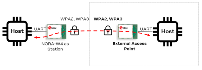
| Nr | Instructions | AT command | AT event |
|---|---|---|---|
| 1 | Set the SSID and select nework channel to 6 to define the frequency band | AT+UWAPCP="NORA-W36 Access Point",6 | |
| 2 | Set the Password, using WPA2 | AT+UWAPSW="mypassword" | |
| 3 | Activate the Wi-Fi Access point. DHCP Server is enabled by default | AT+UWAPA | |
| 4 | Wait for Access Point | +UEWAPU | |
| 5 | Wait for Network interface | +UEWAPNU | |
| 6 | Check the IP address of the AP (optional) | AT+UWAPNST=0 | +UWAPNST:0,192.168.1.80 |
| 7 | Station connected | +UEWAPSA:AAAAAAAAAAAA | |
| 8 | It is now possible to connect over TCP and UDP, and then send and receive data in String or Binary mode. It is also possible to connect MQTT. | ||
| 9 | Station disconnect | +UEWAPSDA:AAAAAAAAAAAA | |
| 10 | Deactivate Wi-Fi Access Point | AT+UWAPD |
 Note: If NORA-W36 activates Wi-Fi Access Point at startup, Activate (
AT+UWAPA), Store (AT&W) and Reset (AT+UWAPA) commands should be sent. The current Wi-Fi Access Point state is stored in flash and NORA-W36 then activates the Access Point using the stored SSID and password at startup.
1.100 + x IP address) as default.
5.3 Wi-Fi TCP client
This use case configures NORA-W36 as a Wi-Fi TCP client device that initiates a TCP connection to a specified server (listener) over a Wi-Fi network. It actively seeks to establish communication by sending a connection request to the server’s IP address and port number, which the server is listening on.
The Transmission Control Protocol (TCP) is bidirectional and one socket can both send and receive data:
ATE0turns off the AT command echo to speed up the data transmission in AT mode. The written data is not echoed back to the host, which helps to make the parsing easier.- It is possible to connect using a host name like
AT+USOC=0,www.u-blox.com,80or an IP addressAT+USOC=0,75.2.60.5,80 - TCP can both send and receive data between the TCP client and server
| Nr | Instructions | AT command | AT event |
|---|---|---|---|
| 1 | Create a TCP socket | AT+USOCR=6 | +USOCR:0 |
| 2 | Connect using TCP port 5003 | AT+USOC=0,192.168.0.200,5003 | +UESOC:0 |
| 3 | It is now possible to send and receive data using String or Binary mode | ||
| 4 | Close TCP socket | AT+USOCL=0 | +UESOCL:0 |
5.4 Wi-Fi TCP server (listener)
This use case configures NORA-W36 as a Wi-Fi TCP server (listener) that is configured to accept incoming TCP connections over a Wi-Fi network. It “listens” on a specific IP address and port number for connection requests.
| Nr | Instructions | AT command | AT event |
|---|---|---|---|
| 1 | Create a TCP socket | AT+USOCR=6 | +USOCR:0 |
| 2 | Start TCP server (listener) on port 5003 | AT+USOL=0,5003 | +UESOC:0 |
| 3 | Incoming TCP connection, a new handle 1 to communicate with the connection | +UESOIC:0,192.168.1.100,1 | |
| 4 | It is now possible to send and receive data using String or Binary mode | ||
| 5 | TCP connection is closed from remote side | +UESOCL:1 | |
| 6 | Close TCP listener | AT+USOCL=0 | +UESOCL:0 |
5.5 Wi-Fi UDP client
Unlike TCP, the User Datagram Protocol (UDP) is not bi-directional. Both an outgoing and incoming socket, AT+USOCR, are needed to send and receive data over UDP.
It is possible to connect using the host name, like AT+USOC=0,www.u-blox.com,80, or the IP address AT+USOC=0,75.2.60.5,80
| Nr | Instructions | AT command | AT event |
|---|---|---|---|
| 1 | Create a UDP socket | AT+USOCR=17 | +USOCR:0 |
| 2 | Connect using UDP port 5003 | AT+USOC=0,192.168.0.200,5003 | +UESOC:0 |
| 3 | It is now possible to send data using String or Binary mode | ||
| 4 | Close UDP socket | AT+USOCL=0 | +UESOCL:0 |
5.6 Wi-Fi UDP server (listener)
| Nr | Instructions | AT command | AT event |
|---|---|---|---|
| 1 | Create a UDP socket | AT+USOCR=17 | +USOCR:0 |
| 2 | Start UDP server (listener) on port 5003 | AT+USOL=0,5003 | +UESOC:0 |
| 3 | It is now possible to receive data using String or Binary mode | ||
| 4 | Close UDP listener | AT+USOCL=0 | +UESOCL:0 |
5.7 Wi-Fi TCP using TLS without certificates
TLS Extensions are enabled by default but in some (mostly older) TLS servers they are not supported. See https://www.rfc-editor.org/rfc/rfc6066.html.
The extensions, Server Name, Indication and Maximum Fragment Length Negotiation, are disabled with:
AT+USETE0=0Server Name Indication, 0: Disable - 1: Enable (default)AT+USETE1=0Maximum Fragment Length Negotiation, 0: Disable - 1: Enable (default)- All other Extension are disabled and not supported.
- It is possible to connect using host name like
AT+USOC=0,www.u-blox.com,80or using ip addressAT+USOC=0,75.2.60.5,80
TCP is bidirectional and one socket can both send and receive data.
| Nr | Instructions | AT command | AT event |
|---|---|---|---|
| 1 | Create a TCP socket | AT+USOCR=6 | +USOCR:0 |
| 2 | Add a TLS context to a socket | AT+USOTLS=0,1 | |
| 3 | Connect using TCP port 433 | AT+USOC=0,www.u-blox.com,433 | +UESOC:0 |
| 4 | It is now possible to send data using String or Binary mode | ||
| 5 | Close TCP socket | AT+USOCL=0 | +UESOCL:0 |
5.8 Wi-Fi TCP using TLS with certificates
TCP is bidirectional and one socket can both send and receive data.
| Nr | Instructions | AT command | AT event |
|---|---|---|---|
| 1 | Write a X.509 certificate and private key using Binary data | AT+USECUB=0,"ca.pem"[send binary content of "ca.pem"]AT+USECUB=1,"client.pem"[send binary content of "client.pem"]AT+USECUB=2,"client.key"[send binary content of "client.key"]See Binary data for more information, note that the brackets "[" and "]" should NOT be sent, they are just here in this example | |
| 2 | Create a TCP socket | AT+USOCR=6 | +USOCR:0 |
| 3 | Add a TLS context to a socket and certificates | AT+USOTLS=0,1,"ca.pem","client.pem","client.key" | |
| 4 | Connect using TCP port 433 | AT+USOC=0,www.u-blox.com,433 | +UESOC:0 |
| 5 | It is now possible to send data using String or Binary mode | ||
| 6 | Close TCP socket | AT+USOCL=0 | +UESOCL:0 |
5.9 Create own certificates using OpenSSL
Here is some example to cerate own certificates using OpenSSL https://www.openssl.org/.
It shows how to use 2048 or 4096 bit keys length.
Use Git Bash https://git-scm.com/download/win or a Linux environment like Ubuntu https://ubuntu.com/download to run the examples.
-
Create the root CA key
Generate 2048 key size:openssl genrsa -out ca.key 2048
or
Generate 4096 key size:openssl genrsa -out ca.key 4096
-
Create the root CA based on ca.key
openssl req -x509 -sha256 -new -nodes -key ca.key -days 3650 -out ca.pem
-
Create server certificate
Create the server certificate signing request (CSR) for 2048 key size:openssl req -newkey rsa:2048 -keyout server.key -out server.csr -nodes
or
Create the server certificate signing request (CSR) for 4096 key size:openssl req -newkey rsa:4096 -keyout server.key -out server.csr -nodes
-
Create the server certificate using root CA and server csr, valid for 10 years
openssl x509 -req -CA ca.pem -CAkey ca.key -in server.csr -out server.pem -days 3650 -CAcreateserial
-
Create client certificate
Create the client certificate signing request (CSR) for 2048 key size:openssl req -newkey rsa:2048 -keyout client.key -out client.csr -nodes
or
Create the client certificate signing request (CSR) for 4096 key size:openssl req -newkey rsa:4096 -keyout client.key -out client.csr -nodes
-
Create the client certificate using root CA and client csr, valid for 10 years
openssl x509 -req -CA ca.pem -CAkey ca.key -in client.csr -out client.pem -days 3650 -CAcreateserial
In a Windows Git Bash enviroment
Set up a local TLS 1.2 server (without CA validation in this case)winpty is a Windows software package providing an interface similar to a Unix pty-master for communicating with Windows console programs.winpty openssl s_server -CAfile ca.pem -key server.key -cert server.pem -accept 44330 -tls1_2 -state -Verify 1
Connect to the a local TLS 1.2 server, just to try the connection (without CA validation in this case):winpty openssl s_client -connect localhost:44330 -CAfile ca.pem -key client.key -cert client.pem -tls1_2
In a Linux enviroment
Set up a local TLS 1.2 server (without CA validation in this case)**openssl s_server -CAfile ca.pem -key server.key -cert server.pem -accept 44330 -tls1_2 -state -Verify 1
Connect to the a local TLS 1.2 server, just to try the connection (without CA validation in this case):openssl s_client -connect localhost:44330 -CAfile ca.pem -key client.key -cert client.pem -tls1_2
Optional steps
Check the key size of the CA certificate:openssl x509 -in ca.pem -text -noout | grep "Public-Key"RSA Public-Key: (4096 bit)
Check the key size of the client certificate:openssl x509 -in client.pem -text -noout | grep "Public-Key"RSA Public-Key: (4096 bit)
Check the size of the client key:openssl rsa -in client.key -text -noout | grep "Private-Key"RSA Private-Key: (4096 bit, 2 primes)
6 MQTT use cases
| Supported modules | Software versions |
|---|---|
| NORA-W36 | v1.0.0 |
- The MQTT client in NORA-W36 uses version MQTT v3.1.1
- For more about the Message Queuing Telemetry Transport (MQTT), see the MQTT beginner’s guide
- The TLS implementation in NORA-W36 supports only version 1.2
6.1 MQTT client without TLS
This use case connects NORA-W36 as a Wi-Fi Station, an Access Point, and a general MQTT Broker on port 1883. In this scenario, the module connects to Mosquito without a certificate.
Parameters and values
- Host: test.mosquitto.org
- Port: 1883 (no TLS connection)
- Client ID: -
- Username: -
- Password: -
- CA Root certificate: -
- Client certificate: -
- Client private key: -
Before connecting to MQTT, set up Wi-Fi Connection, as described in Wi-Fi station, steps 1-5.
| Nr | Instructions | AT command | AT event |
|---|---|---|---|
| 1 | Configure MQTT host and port | AT+UMQCP=0,test.mosquitto.org,1883 | |
| 2 | Connect to MQTT broker | AT+UMQC=0 | +UEMQC:0 |
| 3 | Publish Message on topic pubtopic | AT+UMQP=0,0,0,"pubtopic","Helllo from NORA-W36" | |
| 4 | Subscribe on topic subtopic | AT+UMQS=0,0,"subtopic" | |
| 5 | Post a Message to the MQTT Broker on subtopic the message should be Hello from remote device | - | - |
| 6 | Receive Message on subtopic | +UEMQD:0,24 | |
| 7 | Read String Message | AT+UMQRS=0 | +UMQRS:0,0,"subtopic",24,"Hello from remote device" |
| 8 | Disconnect from MQTT broker | AT+UMQDC=0 |
Note: Use the wildcard "*" to receive messages for all topics. Note that this option may not be supported by all brokers, like Azure.
6.2 MQTT TLS client - Mosquitto

This use case connects NORA-W36 as a Wi-Fi Station and a MQTT Broker. In this scenario, the module connects to Mosquito using certificates.
To generate certificate and keys, follow the procedures described on the Mosquitto web page: https://test.mosquitto.org/ssl/
CA cert: mosquitto.org.crt
Client cert: client.crt
Client key: client.key
Parameters and values
- Host: test.mosquitto.org
- Port: 8884 (TLS)
- Client ID: -
- Username: -
- Password: -
- CA Root certificate: mosquitto.org.crt
- Client certificate: client.crt
- Client private key: client.key
Note: The parameters given in this scenario use the port 8884 for connections and encryption for security.
To authenticate the client and ensure that:
- Only authorized devices can establish a connection with the MQTT broker
- Clients provide a valid certificate when making a connection
- 1883 : MQTT, unencrypted, unauthenticated
- 1884 : MQTT, unencrypted, authenticated
- 8883 : MQTT, encrypted, unauthenticated
- 8884 : MQTT, encrypted, client certificate required (used in this example)
- 8885 : MQTT, encrypted, authenticated
- 8886 : MQTT, encrypted, unauthenticated
Before connecting to MQTT, set up a Wi-Fi Connection like that described in Wi-Fi station, steps 1-5.
| Nr | Instructions | AT command | AT event |
|---|---|---|---|
| 1 | Configure MQTT host and port | AT+UMQCP=0,test.mosquitto.org,8884 | |
| 2 | Write a X.509 certificate and private key using Binary data | AT+USECUB=0,"mosquitto.org.crt"[send binary content of "mosquitto.org.crt"]AT+USECUB=1,"client.crt"[send binary content of "client.crt"]AT+USECUB=2,"client.key"[send binary content of "client.key"]See Binary data for more information, note that the brackets "[" and "]" should NOT be sent, they are just here in this example. | |
| 3 | Setup TLS connection config | AT+UMQTLS=0,1,mosquitto.org.crt","client.crt","client.key" | |
| 4 | Connect to MQTT broker | AT+UMQC=0 | +UEMQC:0 |
| 5 | Publish Message on topic pubtopic | AT+UMQP=0,0,0,"pubtopic","Helllo from NORA-W36" | |
| 6 | Subscribe on topic subtopic | AT+UMQS=0,0,"subtopic" | |
| 7 | Post a Message to the MQTT Broker on subtopic. The message should say Hello from remote device | - | - |
| 8 | Receive Message on subtopic | +UEMQD:0,24 | |
| 9 | Read String Message | AT+UMQRS=0 | +UMQRS:0,0,"subtopic",24,"Hello from remote device" |
| 10 | Disconnect from MQTT broker | AT+UMQDC=0 |
6.3 MQTT TLS client - Thingstream

This use case connects NORA-W36 as a Wi-Fi Station and a MQTT Broker. In this scenario NORA-W36 connects to Thingstream using a CA Root certificate, Client-ID, Username and Password.
thingstream.io uses the AWS Root Certificate found here
Before connecting to MQTT, set up Wi-Fi Connection, like that described Wi-Fi station, steps 1-5.
The parameters and values necessary for the the use case include:
Parameters and values
- Host: mqtt.thingstream.io
- Port: 8883 (TLS)
- Client ID: device:78e3d356-876f-483b-872f-3485853fAAAA
- Username: HMVK8C09FQP245O2BBBB
- Password: ofYyBB/L3GkPvo060J6Dv+t+mfrh0XpGMcf7CCCC
- CA Root certificate: AmazonRootCA1.pem
- Client certificate: -
- Client private key: -
Before connecting to MQTT, set up Wi-Fi Connection like in steps 1-5 in Wi-Fi station
| Nr | Instructions | AT command | AT event |
|---|---|---|---|
| 1 | Configure the MQTT host, port, client-ID, username and passsword | AT+UMQCP=0,mqtt.thingstream.io,8883,device:78e3d356-876f-483b-872f-3485853fAAAA,HMVK8C09FQP245O2BBBB,ofYyBB/L3GkPvo060J6Dv+t+mfrh0XpGMcf7CCCC | +UEMQC:0 |
| 2 | Write a X.509 CA Root certificate using Binary data | AT+USECUB=0,"AmazonRootCA1.pem"[send binary content of "AmazonRootCA1.pem"]See Binary data for more information, note that the brackets "[" and "]" should NOT be sent, they are just here in this example | |
| 3 | Set up TLS connection config. Thingstream doesn´t use a client certificate or key - only the root CA. | AT+UMQTLS=0,1,AmazonRootCA1.pem" | |
| 4 | Connect to MQTT broker | AT+UMQC=0 | +UEMQC:0 |
| 5 | Publish a message on pubtopic | AT+UMQP=0,0,0,"pubtopic","Helllo from NORA-W36" | |
| 6 | Subscribe on topic subtopic | AT+UMQS=0,0,"subtopic" | |
| 7 | Post a message to the MQTT broker on subtopic. The message should say Hello from remote device | - | - |
| 8 | Receive a message on subtopic | +UEMQD:0,24 | |
| 9 | Read String Message | AT+UMQRS=0 | +UMQRS:0,0,"subtopic",24,"Hello from remote device" |
| 10 | Disconnect from MQTT broker | AT+UMQDC=0 |
6.4 MQTT TLS client - AWS IoT Core
Connect as a Wi-Fi Station and a MQTT Broker. In this scenario, NORA-W36 connects to Amazon AWS IoT Core using certificates.
Parameters and values
- Host: a3loryode2aaaa-ats.iot.us-east-2.amazonaws.com
- Port: 8883 (TLS)
- Client ID: -
- Username: -
- Password: -
- CA Root certificate: AmazonRootCA1.pem
- Client certificate: aws_client.crt
- Client private key: aws_priv_key.key
Before connecting to MQTT, set up Wi-Fi Connection like in steps 1-5 in Wi-Fi station
| Nr | Instructions | AT command | AT event |
|---|---|---|---|
| 1 | Configure MQTT host and port | AT+UMQCP=0,a3loryode2aaaa-ats.iot.us-east-2.amazonaws.com,8883 | |
| 2 | Write a X.509 certificate and private key using Binary data | AT+USECUB=0,"AmazonRootCA1.pem"[send binary content of "AmazonRootCA1.pem"]AT+USECUB=1,"aws_client.crt"[send binary content of "aws_client.crt"]AT+USECUB=2,"aws_priv_key.key"[send binary content of "aws_priv_key.key"]See Binary data for more information, note that the brackets "[" and "]" should NOT be sent, they are just here in this example | |
| 3 | Setup TLS connection config | AT+UMQTLS=0,1,"AmazonRootCA1.pem","aws_client.crt","aws_priv_key.key" | |
| 4 | Connect to MQTT broker | AT+UMQC=0 | +UEMQC:0 |
| 5 | Publish Message on topic pubtopic | AT+UMQP=0,0,0,"pubtopic","Helllo from NORA-W36" | |
| 6 | Subscribe on topic subtopic | AT+UMQS=0,0,"subtopic" | |
| 7 | Post a Message to the MQTT Broker on subtopic the message should be Hello from remote device | - | - |
| 8 | Receive Message on subtopic | +UEMQD:0,24 | |
| 9 | Read String Message | AT+UMQRS=0 | +UMQRS:0,0,"subtopic",24,"Hello from remote device" |
| 10 | Disconnect from MQTT broker | AT+UMQDC=0 |
6.5 MQTT TLS client - Azure IoT Hub
Connect as a Wi-Fi Station and an Access Point and a MQTT Broker. In this scenario, NORA-W36 connects to Microsoft Azure using certificates.
Note that Azure IoT Hub isn't a full-featured MQTT broker and doesn't support all the behaviors specified in the MQTT v3.1.1 standard
Parameters and values
- Host: iothub-test-sw.azure-devices
- Port: 8883 (TLS)
- Client ID: device1
- Username: iothub-test-sw.azure-devices.net/device1/
- Password: -
- CA Root certificate: AzureCa.pem
- Client certificate: azure_client.crt
- Client private key: azure_priv_key.key
Before connecting to MQTT, set up Wi-Fi Connection like in steps 1-5 in Wi-Fi station
| Nr | Instructions | AT command | AT event |
|---|---|---|---|
| 1 | Configure MQTT Host, Port, Cient and Usename | AT+UMQCP=0,iothub-test-sw.azure-devices.net,8883,device1,iothub-test-sw.azure-devices.net/device1 | |
| 2 | Write a X.509 certificate and private key using Binary data | AT+USECUB=0,"AzureCa.pem"[data binary content of "AzureCa.pem"]AT+USECUB=1,"azure_client.crt"[data binary content of "azure_client.crt"]AT+USECUB=2,"azure_priv_key.key"[data binary content of "azure_priv_key.key"]See Binary data for more information, note that the brackets "[" and "]" should NOT be sent, they are just here in this example | |
| 3 | Setup TLS connection config | AT+UMQTLS=0,1,AzureCa.pem","azure_client.crt","azure_priv_key.key" | |
| 4 | Connect to MQTT broker | AT+UMQC=0 | +UEMQC:0 |
| 5 | Publish Message on topic pubtopic | AT+UMQP=0,0,0,"pubtopic","Helllo from NORA-W36" | |
| 6 | Subscribe on topic subtopic | AT+UMQS=0,0,"subtopic" | |
| 7 | Post a Message to the MQTT Broker on subtopic the message should be Hello from remote device | - | - |
| 8 | Receive Message on subtopic | +UEMQD:0,24 | |
| 9 | Read String Message | AT+UMQRS=0 | +UMQRS:0,0,"subtopic",24,"Hello from remote device" |
| 10 | Disconnect from MQTT broker | AT+UMQDC=0 |
7 Send and receive data
NORA-W36 supports several modes for sending and receiving data:
- String mode
- All readable ASCII characters (
0x21-0x7E,0xA1-0xFF) - Use when sending data in plain text format. For example, when using JSON, HTML, or NMEA.
- All readable ASCII characters (
- Binary mode
- All types of characters (
0x00-0xFF) - Use when all types of data is needed. For example, in binary content using file upload and download.
- All types of characters (
- Transparent mode
- All types of characters (
0x00-0xFF)
- All types of characters (
- Transparent mode has best performance, due to no wait states
- Direct mode is faster than Buffered mode
- Binary mode is faster than String mode
To receive data without an event and read it out, the read mode can be changed to direct mode AT+USORM=1
7.1 String mode
Socket receive mode
SyntaxAT+USORM=<receive_mode>
- 0: Buffered mode
+UESODA- Socket Data Available Event, default mode
- 1: Direct string mode
+UESODS- Socket Data Binary Event: Incoming on TCP socket data represented as a string+UESODSF- Socket Data Binary From Event: Incoming on UDP socket data represented as a string
SPS Receive data mode
SyntaxAT+USPSRM=<receive_mode>
- 0: Buffered mode
+UESPSDASPS Data Available event, default mode
- 1: Direct string mode
+UESPSDS- SPS Data String event
7.1.1 Socket write string
SyntaxAT+USOWS=<socket_handle>,<string_data>
Example to write socket data
| Nr | Instructions | AT command | AT event |
|---|---|---|---|
| 1 | Write Socket data in string format size | AT+USOWS=0,"Hello from NORA-W36" |
7.1.2 Socket read string
SyntaxAT+USORS=<socket_handle>,<length>+USORS:<socket_handle>,<length>,<string_data>
Example to read socket data
| Nr | Instructions | AT command | AT event |
|---|---|---|---|
| 1 | Incoming Socket data | +UESODA:0,19 | |
| 2 | Reads incoming Socket data in string format | AT+USORS=0,19 | +USORS:0,19,"Hello from NORA-W36" |
7.1.3 SPS write string
SyntaxAT+USPSWS=<conn_handle>,<string_data>
Example to write SPS data
| Nr | Instructions | AT command | AT event |
|---|---|---|---|
| 1 | Write SPS data in string format size | AT+USPSWS=0,"Hello from NORA-W36" |
7.1.4 SPS read string
SyntaxAT+USPSRS=<socket_handle>,<length>+USPSRS:<socket_handle>,<length>,<string_data>
Example to read SPS data
| Nr | Instructions | AT command | AT event |
|---|---|---|---|
| 1 | Incoming SPS data | +UESPSDA:0,19 | |
| 2 | Reads incoming SPS data in string format | AT+USPSRS=0,19 | +USPSRS:0,19,"Hello from NORA-W36" |
7.2 Binary mode
The binary mode should be used when binary conent is transmitted, like files and binary protocols.
See Binary data for more infomation about the format of th data.
Socket receive mode
SyntaxAT+USORM=<receive_mode>
- 0: Buffered mode
+UESODA- Socket Data Available Event, default mode
- 2: Direct binary mode
+UESODB- Socket Data Binary Event: Incoming on TCP socket data represented as binary data+UESODBF- Socket Data Binary From: Incoming on UDP socket data represented as binary data
SPS receive mode
SyntaxAT+USPSRM=<receive_mode>
- 0: Buffered mode
+UESPSDASPS Data Available event, default mode
- 2: Direct binary mode
+UESPSDB- SPS Data Binary event
See more infomation about Binary Data.
7.2.1 Socket write binary
AT+USOWB=<socket_handle><binary_header><binary_data>
Example to write socket data
| Nr | Instructions | AT command | AT event |
|---|---|---|---|
| 1 | Write Socket data in binary format size | AT+USOWS=0\x01\x00\x13Hello from NORA-W36 |
7.2.2 Socket read binary
SyntaxAT+USORB=<socket_handle>,<length>
+USORS:<socket_handle><binary_header><binary_data>
Example to read socket data
| Nr | Instructions | AT command | AT event |
|---|---|---|---|
| 1 | Incoming Socket data | +UESODA:0,19 | |
| 2 | Reads incoming Socket data in binary format | AT+USORB=0,19 | +USORB:0\x01\x00\x13Hello from NORA-W36 |
7.2.3 SPS write binary
SyntaxAT+USPSWS=<conn_handle><binary_header><binary_data>
Example to write SPS data
| Nr | Instructions | AT command | AT event |
|---|---|---|---|
| 1 | Write SPS data in binary format size | AT+USPSWB=0\x01\x00\x13Hello from NORA-W36 |
7.2.4 SPS read binary
SyntaxAT+USORB=<socket_handle>,<length>
+USORB:<socket_handle><binary_header><binary_data>
Example to read SPS data
| Nr | Instructions | AT command | AT event |
|---|---|---|---|
| 1 | Incoming SPS data | +UESPSDA:0,19 | |
| 2 | Reads incoming SPS data in binary format | AT+USPSRB=0,19 | +USPSRB:0\x01\x00\x13Hello from NORA-W36 |
7.3 Transparent mode
Transparent mode (TM) works in the same way as Data mode in legacy products. Note that only one connection of TCP, UDP (Wi-Fi), or SPS (BLE) is allowed.
To enter Transparent Mode the AT command AT+UTM are used and the option is to use TCP, UDP, or SPS.
SyntaxAT+UTM=<link_type>,<handle>
Example for SPSAT+UTM=0,0OK
Transparent mode has started+++OK
Back in AT mode
Example for TCP socketAT+UTM=1,0OK
Transparent mode has started+++OK
Back in AT mode
Until the escape secqence +++ is send, all data will received on the UART will be sent unmodified to the remote device on the specific connection selected.
7.4 Transparent mode persistent
Like the Transparent Mode (TM) the Transparent Mode Persistent (TMP) works in the same way as Data Mode in legacy products. Note that only one connection of TCP, UDP (Wi-Fi), or SPS (Bluetooth LE) is allowed.
The only difference with TM and TMP is that TMP can be stored in flash and connect at startup.
To enter TMP, the AT+UTMP command is used - optionally with TCP, UDP, or SPS.
SyntaxAT+UBTP=<bd_addr>,<connect_sps>AT+UTMP=<link_type>,<config_id>
Example for SPS
| Nr | Instructions | AT command | AT event |
|---|---|---|---|
| 1 | Enter the remote Bluetooth LE address to connecting device | AT+UBTP=BBBBBBBBBBBB,1 | +UBTP:200 |
| 2 | Enable Persistant on the connection | AT+UTMP=0,200 | |
| 3 | Store settings | AT&W | |
| 4 | Reset the module | AT+CPWROFF | |
| 5 | Wait for NORA-W36 to startup | +STARTUP | |
| 6 | Transparent Mode Persistent has started | ||
| 7 | Exit Transparent Mode using escape sequence | +++ |
Example for TCP socket
| Nr | Instructions | AT command | AT event |
|---|---|---|---|
| 1 | Create a Peristent TCP Socket | AT+USOPCR=6 | +USOPCR:100 |
| 2 | Set the Ip Address and Port for the connection | AT+USOP=100,192.168.0.26,5003 | |
| 3 | Enable Persistant on the connection | AT+UTMP=1,100 | |
| 4 | Set up Wi-Fi Connection like in steps 1-5 in Wi-Fi station | ||
| 5 | Store settings | AT&W | |
| 6 | Reset the module | AT+CPWROFF | |
| 7 | Wait for NORA-W36 to startup | +STARTUP | |
| 8 | Transparent Mode Persistent has started | ||
| 9 | Exit Transparent Mode using escape sequence | +++ |
Until the escape sequence +++ is sent, all data will received on the UART will be sent unmodified to the remote device on the specific connection selected.
8 Binary data
The packet starts with \x01 (SOH, Start Of Header) followed by the length of the data in two-byte unsigned integer (UINT16) format, and then followed by the binary data.
The data must not be terminated with the normal \x0D (\r - Carriage Return).
The binary header comprises three bytes:[0x01(SOH Start Of Header), MSB_datalength, LSB_datalength]
All commands and Unsolicited Result Codes (URC) that use binary data are "complete" without the binary data. In most cases, the binary data is sent directy after the AT command and the handle.
In the following [AT+USOWB] Socket Write Binary command example, the binary data follows the the socket handle directly - without "," or "\r" or any other character in between.
Example:AT+USOWB=0[0x01,0x00,0x02,0xFF,0xEE]
This command writes to socket 0, 2 bytes data the data is 0xFF 0xEE.
Binary data for the Socket, SPS, and certicitate upload all use the same Binary data format.
8.1 Binary mode command example
To send the following Hello from NORA-W36 message, the content must have a length of 19 bytes. The length in UINT16 format is \00\x13.
AT+USOWB=0\x01\x00\x13Hello from NORA-W36
Note that the AT command must not be terminated with the \r, The length shown in the header defines the number of bytes expected from the AT parser. The complete AT event includes the same three bytes header immediately after the handle in the event, like this:+USORB:0\x01\x00\x13Hello from NORA-W36
8.2 Certificate upload command example
In the following example, the Security Certificate Upload Binary command, AT+USECUB, is entered with the X.509 certificate (or private key) using binary transfer. The certificate length is 1342 bytes and given in UINT16 format as \05\x3E.
To send the content of
-----BEGIN CERTIFICATE-----\nABCDojCCAoqgAwIBAgIBADANBgkqhkiG9w0BAQsFADCBkDELMAkGA1UEBhMCR0Ix\nFzAVBgNVBAgMDlVuaXRlZCBLaW5nZG9tMQ4wDAYDVQQHDAVEZXJieTESMBAGA1UE\nCgwJTW9zcXVpdHRvMQswCQYDVQQLDAJDQTEWMBQGA1UEAwwNbW9zcXVpdHRvLm9y\nZzEfMB0GCSqGSIb3DQEJARYQcm9nZXJAYXRjaG9vLm9yZzAeFw0yMzEwMDQxMDEw\nMzJaFw0yNDAxMDIxMDEwMzJaMHwxCzAJBgNVBAYTAlNFMQ4wDAYDVQQIDAVNYWxt\nbzEOMAwGA1UEBwwFTWFsbW8xDzANBgNVBAoMBnUtYmxveDEPMA0GA1UECwwGQUUt\nU0hPMQ0wCwYDVQQDDARjbWFnMRwwGgYJKoZIhvcNAQkBFg10ZXN0QHRlc3Qub3Jn\nMIIBIjANBgkqhkiG9w0BAQEFAAOCAQ8AMIIBCgKCAQEA3PZc1E7uSBiB/Es1V0pU\nXeSayY3f6vrIbnSGTb+/PERSPgPz6UoZumJjcOWbCMq7T+/dvvxox/ZU/t/XdGMq\nMJRgN+aWRG6I4QmqYgkiAZGMuaMa+TLLEEPvL1IDKSxeVjHRNDx4yZM4zgvl6ZX7\noRaBqZBooNTHOtAGjlydyyz55HCZfLsE8Z3iaH7uW+/n9+2nWusfUXoJmI0STmEH\npJ+ZF7M+o53UilW2NKdv/R+wCzXxmKWX6PFVg4NdKspTDUOpPcxlphMQGi24E2uz\n2k7raCQvGt32LxZc/vic4W6rNDGGNSSDVJTSx6egzfRrcCKw3T88TN87nasjc+KV\nCQIDAQABoxowGDAJBgNVHRMEAjAAMAsGA1UdDwQEAwIF4DANBgkqhkiG9w0BAQsF\nAAOCAQEAjRyNWHGtcwLT21IzJ2//I8YL611iTUitRGkA0gF+7l0DuPtfSLPVhoyB\nTe3FThYsn2OYfF+LrbSMlWO38Am2fqE8lTGe9EX/HZj95Wj+RnQApc9CkxGJkCb8\n6aecuz8Vhyl2zWA5kqNrq978uMmsyX3FNRcS3mB7Vo+65R/XwThzHjSXyCyHzRMd\nzOlrJZMuNWV2bI7vyIIp9/AdHNO6Hwnj+I5hBDvyV+T9RT2jLUTRZldGUJQBlDVj\nQUKa8NSwzVrvoVTPAT6gcPCn4VQkwxLE/LWaNw2X8mxtyo3nXVoo291TzB8mKHUQ\nubOA1iBEcKtAFjqOlZSLanVNvrn5KwXY\n-----END CERTIFICATE-----\n
the certificate have the length of 1342 bytes,
and the length in UINT16 format will be \05\x3E.
This is how the complete AT command will look like
AT+USECUB=0,"ca.pem"\x01\x05\x3E-----BEGIN CERTIFICATE-----\nABCDojCCAoqgAwIBAgIBADANBgkqhkiG9w0BAQsFADCBkDELMAkGA1UEBhMCR0Ix\nFzAVBgNVBAgMDlVuaXRlZCBLaW5nZG9tMQ4wDAYDVQQHDAVEZXJieTESMBAGA1UE\nCgwJTW9zcXVpdHRvMQswCQYDVQQLDAJDQTEWMBQGA1UEAwwNbW9zcXVpdHRvLm9y\nZzEfMB0GCSqGSIb3DQEJARYQcm9nZXJAYXRjaG9vLm9yZzAeFw0yMzEwMDQxMDEw\nMzJaFw0yNDAxMDIxMDEwMzJaMHwxCzAJBgNVBAYTAlNFMQ4wDAYDVQQIDAVNYWxt\nbzEOMAwGA1UEBwwFTWFsbW8xDzANBgNVBAoMBnUtYmxveDEPMA0GA1UECwwGQUUt\nU0hPMQ0wCwYDVQQDDARjbWFnMRwwGgYJKoZIhvcNAQkBFg10ZXN0QHRlc3Qub3Jn\nMIIBIjANBgkqhkiG9w0BAQEFAAOCAQ8AMIIBCgKCAQEA3PZc1E7uSBiB/Es1V0pU\nXeSayY3f6vrIbnSGTb+/PERSPgPz6UoZumJjcOWbCMq7T+/dvvxox/ZU/t/XdGMq\nMJRgN+aWRG6I4QmqYgkiAZGMuaMa+TLLEEPvL1IDKSxeVjHRNDx4yZM4zgvl6ZX7\noRaBqZBooNTHOtAGjlydyyz55HCZfLsE8Z3iaH7uW+/n9+2nWusfUXoJmI0STmEH\npJ+ZF7M+o53UilW2NKdv/R+wCzXxmKWX6PFVg4NdKspTDUOpPcxlphMQGi24E2uz\n2k7raCQvGt32LxZc/vic4W6rNDGGNSSDVJTSx6egzfRrcCKw3T88TN87nasjc+KV\nCQIDAQABoxowGDAJBgNVHRMEAjAAMAsGA1UdDwQEAwIF4DANBgkqhkiG9w0BAQsF\nAAOCAQEAjRyNWHGtcwLT21IzJ2//I8YL611iTUitRGkA0gF+7l0DuPtfSLPVhoyB\nTe3FThYsn2OYfF+LrbSMlWO38Am2fqE8lTGe9EX/HZj95Wj+RnQApc9CkxGJkCb8\n6aecuz8Vhyl2zWA5kqNrq978uMmsyX3FNRcS3mB7Vo+65R/XwThzHjSXyCyHzRMd\nzOlrJZMuNWV2bI7vyIIp9/AdHNO6Hwnj+I5hBDvyV+T9RT2jLUTRZldGUJQBlDVj\nQUKa8NSwzVrvoVTPAT6gcPCn4VQkwxLE/LWaNw2X8mxtyo3nXVoo291TzB8mKHUQ\nubOA1iBEcKtAFjqOlZSLanVNvrn5KwXY\n-----END CERTIFICATE-----\n
+USECUB:1342
OK
Note that the AT command must not be terminated with the \r. The length of the header defines the number of bytes expected from the AT parser.
8.3 Python pseudo code example
byte = 'AT+USECUB=0,"ca.pem"'
byte += b'\x01'
byte += len(bin_data).to_bytes(2, 'big')
byte += bin_data # bin_data contains the binary data to be sent
write(byte)
8.4 C# Pseudo code example
byte[] bin_data' //data contains the binary data to be sent
byte[] dataHeader = new byte[3];
dataHeader[0] = 0x01;
dataHeader[1] = Convert.ToByte(bin_data.Length >> 8);
dataHeader[2] = (Convert.ToByte(bin_data.Length & 0xff));
write("AT+USECUB=0,"ca.pem")
write(dataHeader)
write(bin_data)
9 Diagnosic tools
Diagnostic tools such as ping, which verifies connectivity at the IP level, and iperf, which measures network performance, are useful for troubleshooting and optimizing the communication efficiency in the module.
9.1 Ping
SyntaxAT+UDGP=<destination>[,<count>]
Ping example
| Nr | AT command | AT event |
|---|---|---|
| 1 | AT+UDGP=www.google.com,4 | |
| 2 | +UEDGP:1,15 | |
| 4 | +UEDGP:1,15 | |
| 5 | +UEDGP:1,14 | |
| 6 | +UEDGP:1,14 | |
| 7 | +UEDGPC:4,4,0,14 |
9.2 iperf
Iperf version 2 is supported as client and server software - with support for TCP and UDP data.
Download Iperf 2 for Windows here
Manual for iperf 2 can be found here
Note that the Iperf implementation is exprimental and may change between releases, like parameters and behavior.
SyntaxAT+UDGI=<iperf_action>,<protocol_type>[,<role>,<port>,<report_interval>[,<time_boundary>,<ip_addr>[,<bidirectional>]]]
9.3 Iperf server
Example for Iperf server on port 5001
| Nr | AT command | AT event |
|---|---|---|
| 1 | AT+UDGI=1,1,1,5001,1 | |
| 2 | +UEDGI:"TCP: Start TCP server!" | |
| 3 | +UEDGI:"tcp_server_func: Create socket fd = 0" | |
| 4 | +UEDGI:"tcp_server_func: Bind socket successfully" | |
| 5 | +UEDGI:"tcp_server_func: Listen port 5001" |
9.4 Iperf client
Example for Iperf client to connect on address 192.168.0.41 on port 5001
| Nr | AT command | AT event |
|---|---|---|
| 1 | AT+UDGI=1,1,2,5001,1,20,192.168.0.41 | |
| 2 | +UEDGI:"tcp_client_func: Create socket fd = 1" | |
| 3 | +UEDGI:"tcp_client_func: Connect to server successfully" | |
| 4 | +UEDGI:"tcp_client_func: Send 1435 KBytes in 1000 ms, 11761 Kbits/sec" | |
| 5 | +UEDGI:"tcp_client_func: Send 1418 KBytes in 1000 ms, 11621 Kbits/sec" | |
| 6 | +UEDGI:"tcp_client_func: Send 1417 KBytes in 1000 ms, 11609 Kbits/sec" |
10 Error codes
The Extended error codes can be usefull to understand the reason for the ERROR received.
Note that the error codes should only be used for infomation and might change between version in the future.
10.1 Extended error code
AT+USYEC
SyntaxAT+USYEC?
+USYEC:<error_code>
ExampleAT+USYEC?
+USYEC:5
OK
The error code for 5 is U_ERROR_COMMON_INVALID_PARAMETER, meaning that the parameter on the last AT command was invalid.
See NORA-W36 u-connectXpress Error codes for more details.
10.2 Extended error codes on/off
This command will enable the error code when an ERROR is received for every commands.
SyntaxAT+USYEE=<extended_errors>
ExampleAT+USYEE=1
OK
AT+
ERROR:32
The error code for 32 is U_AT_STATUS_INVALID_COMMAND, meaning that the AT command is not correct.
See NORA-W36 u-connectXpress Error codes for more details.
10.3 Socket error
Use this command to get the last error on the Socket used.
SyntaxAT+USOE
+USOE:<error_code>
ExampleAT+USOE
+USOE:107
The error code for 107 is Transport endpoint is not connected, meaning that the socket connection is down.
See NORA-W36 u-connectXpress Error codes for more details.
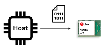
11 Software update
This use case shows what AT commands to send to start a software update.
There are two ways to start the software update:
- See more about the XMODEM protocol here
11.1 Update software by AT command
- Enter XMODEM mode for u-connect software update using serial port
- XMODEM-1K and baud rate up to 3 Mbps is supported.
| Nr | Instructions | AT command | AT event |
|---|---|---|---|
| 1 | Start XMODEM protocol with AT command | AT+USYFWU=0,3000000 | |
| 2 | Now NORA-W36 is ready to receive the software using the XMODEM or XMODEM-1K protocol | � | CCCCCCCCCCC... |
| 3 | When the software has been downloaded the module will restart | +STARTUP | |
| 4 | Check the version of the software | AT+GMR | "1.0.0-001" |
11.2 Update software by bootloader
Consider the following points when updating the software using the bootloader:
- Enter the bootloader command line mode using serial port by AT command
- Press SWITCH_1 and SWITCH_2 during startup (or after reset)
- A command must be sent within 10 seconds when in bootloader command line mode. Otherwise, the device reboots in normal mode
- For the complete list of available commands, enter
? - An XMODEM protocol timeout is invoked after 10 seconds if nothing is received
- XMODEM-1K and baud rate up to 3 Mbps is supported
| Nr | Instructions | AT command | Event |
|---|---|---|---|
| 1a | Enter the bootloader | AT+USYFWU=1,115200 | |
| 1b | Alternatively, press SWITCH_1 and SWITCH_2 during startup or reset to enter the bootloader reset | ||
| 2 | Wait for the > prompt | > | |
| 3 | Change baud rate to up to 3 Mbit/s (optional) | r 3000000 | |
| 4 | Start XMODEM protocol with the command x | x | |
| 5 | Now NORA-W36 is ready to receive the software using the XMODEM or XMODEM-1K protocol | CCCCCCCCCCC... | |
| 6 | Wait for the prompt to indicate that the software has been downloaded successfully | > | |
| 7 | Enter the q command to restart the module | q | |
| 8 | Wait for the prompt to display that the module has restarted in AT mode | +STARTUP | |
| 9 | Check the version of the software | AT+GMR | "1.0.0-001" |
12 Related information
| Resource | Link |
|---|---|
| NORA-W36 product page | https://www.u-blox.com/en/product/nora-w36-series |
| s-center 2 webpage | https://www.u-blox.com/en/product/s-center |
| NORA-W36 AT command manual | https://www.u-blox.com/en/sho-online-documentation/nora-w36/at-manual |
| NORA-W36 Error codes | (https://www.u-blox.com/en/sho-online-documentation/nora-w36/error-codes |